Saturday, November 30, 2013

Automatic Automotive Burglar Alarm

Alarm triggers on after a 13 second delay and stays on for 1-1 Vfe minutes. Then it resets automatically It can also be turned off and reset by opening and reclosing SI.

Automotive Burglar Alarm Circuit Diagram
Automotive Alarm Circuit Diagram

Read More..

2x70Watt Amplifier Circuit

Stereo Power Amplifier is 2x70Watt STA550 chip audio power with BASH concept that can be connected with digital perangkkat. 2x70Watt STA550 Stereo Power Amplifier is an amplifier with BTL system with symmetrical power supply with ground. Power amplifier STA550 uses power output transistor which is on the chip and is set to produce a high efficiency audio power.
Power output on the STA550 is using the system without copling ac bridge (direct) and zero offset. Strengthening of the STA550 from stereo power amplifier is +12 dB. 2x70Watt STA550 Stereo Power Amplifier is equipped with temperature sensors for protection from overheating and current-limiting protection system for power amplifier. 2x70Watt STA550 Stereo Power Amplifier is equipped with standby and mute controls to regulate silent or active mode power amplifier.
2x70Watt Amplifier Circuit


Feature Stereo Power Amplifier 2x70Watt STA550 :
Monochip Bridge Stereo Amplifier dengan Bash® Architecture
55+55w Output Power @ Rl = 4/8 W, Thd = 0.5%
70+70w Output Power @ Rl = 4/8 W, Thd = 10%
High Dynamic Preamplifier Input Stages
External Programmable Feedback Type Compressors
Ac Coupled Input To Class Ab Bridge Output Amplifier
Precision Rectifiers To Drive The Digital Converter
Proportional Over Power Output Current To Limit The Digital Converter
Absolute Power Bridge Output Transistor Power Protection
Absolute Output Current Limit
Integrated Thermal Protection
Power Supply Over Voltage Protection Flexiwatt Power Package With 27 Pin
Bash® Licence Required
Read More..

Subowoofer audio car amplifier

For the a one amplifier circuit is very suitable for use in applications subwoofer speaker, which allows for higher spending enough bass. Although output was spent not high, but for bass sounds do not undoubtedly. Indeed, the output is only 20W mono amplifier with 8 ohm impedance. With a maximum supply 44Volt DC.
car subwoofer
Part list
R1 = 47R
R2 = 100K
R3 = 1R 2W
C1 = 2.2uF
C2 = 220uF
C3 = 100uF
C4 = 47uF
C5 = 68uF
C6 = 100uF
C7 = 1000uF
C8 = 0.1uF
U1 = STK024 , STK031 ,STK035
Read More..

Beat Balance Metal Detector

A Beat Balance Metal Detector made from discrete components.

Beat Balance Metal Detector Schematic


Notes:

Various embodiments of the BB metal detector have been published, and it has been widely described in the press as a new genre. Instead of using a search and a reference oscillator as with BFO, or Tx and Rx coils as with IB, it uses two transmitters or search oscillators with IB-style coil overlap. The frequencies of the two oscillators are then mixed in similar fashion to BFO, to produce an audible heterodyne. On the surface of it, this design would seem to represent little more than a twinned BFO metal detector. However, what makes it different above all else, and significantly increases its range, is that each coil modifies the frequency of the adjacent oscillator through mutual coupling. This introduces the "balance" that is present in an IB metal detector, and boosts sensitivity well beyond that of BFO. Since the concept borrows from both BFO and IB, I have given a nod to each of these by naming it a Beat Balance Metal Detector, or BB for short. Happy hunting!
Read More..

Friday, November 29, 2013

Cheap Electronics Component for Amplifier Application

cheap electronics
Cheap electronics component for amplifier application, it is simple to be made for speaker active . The sound quality even this  Mini Amplifier TDA2030 quite satisfactory for a portable audio system.


"The series of Mini Amplifier TDA 2030 "The series of mini amplifie can reproduce the power output of 14 Watt with 8 Ohm speaker load. The series of mini-amplifier can be supplied with ource voltage of 12 volts - 15 volts DC. more details, see the following series of pictures.

cheap electronics

Daftar komponen
Resistor:

- R1: 150KΩ
- R2: 4.7KΩ
- R3: 100KΩ
- R4: 1Ω 1W
- RA/RB: 100KΩ

Capacitor

- C1: 1µF / 25V
- C2: 2.2µF / 25V
- C3: 100nF
- C4: 22µF / 25V
- C5: 100 µF / 25V
- C6: 220nF
- C7: 2200µF / 35V

IC / Dioda

- IC1: TDA2030 or TDA2030a
- D1/D2: IN4002
Read More..

Active AM Radio Antenna Amplifier Preamplifier Circuit

Active AM Radio Antenna Amplifier / Preamplifier CircuitActive AM Radio Antenna Amplifier / Preamplifier Circuit


The antenna amplifier circuit has a part count of about 40, using the following active parts: 2 NPN transistors (BC548s), 1 MOSFET (BF981), 2 Varicap diodes (KV1235), as well as a 6v2 zener-diode. there is and a 330uH (micro Henry) inductor / coil, which can be modified for operation on other frequency bands.


Modelsed to work with a telescopic whip antenna, the amplifier circuit operates in the typical AM / MediumWave band of 550 - 1650 kHz (kilohertz), with a power requirement of 12 Volts DC. The circuit also has a gain control feature, so weather signals can be amplifier more, if need be. This amplification alteration is provided via, RV1


The amplifier circuits output impedance is 50 Ohms, which is the standard for all of radio receivers, so it ought to work well along with your AM receiver.


Notes

This circuit is designed to amplify the input from a telescopic whip antenna. The preamplifier is designed to cover the medium waveband from about 550Khz to 1650Khz. The tuning voltage is supplied via RV2, a 10k potentiometer connected to the 12 Volt power supply.


RV1 is the gain control allowing weak signals to be amplified or strong signals to be attenuated. The control voltage is applied to gate 2 of TR1, a dual-gate MOSFET, the signal voltage applied via gate 1; the input signal being double tuned via the 330uH coil and the two KV1235 varicap diodes at the MOSFETs input and by the same components at the BF981 MOSFETs drain terminal. Both tuned circuits provide high selectivity across the entire tuning range. To aid stability the MOSFET stage is fed from a 6.2V zener stabilized supply.


To drive low impedance (50 ohm) receivers, the medium output impedance of the BF981 stage is enhanced by the composite amplifier made from Q2 and Q3. Q2 is operating in common emitter boosting voltage levels by just over 2, Q3 is operating in emitter follower providing the circuit with low output impedance.


Finally this active antenna can be used on other bands by changing the values of the 330uH coils. To perform on multiple bands switches or relays can be used to change the value of the coils.

Read More..

Simple FM transmitter with 2N3904

simple FM transmitter
In this section discuss about the series of mini fm transmitter, with broadcast coverage of about 300-400 meters. when using a 9 volt working voltage, the transmit power of about 300 meters and when using the working voltage 12 volts, the range of about 400-450 meters, depending on the antenna you use.

This scheme of simple fm transmitter
simple FM transmitter

For L1 and L2 windings 5 times the wrap, you can use a pen to fill melilitnya so neat and after lepaslah content of these pens. C5 is used for placement of broadcasting frequencies, can be tuned between 88-108 mhz, to reach further use steering antenna or Yagi antenna.

Part List
C1 = 0.001uF
C2 = 5.6pF
C3 = 10uF
C4 = 10uF
C5 = 3 - 18pF Adjustable capacitor
R1 = 270R
R2 = 4.7K
R3 = 10K
R4 = 100K
R5 = 4.7K
R6 = 4.7K
Q1 = 2N2222A
Q2 = 2N3904
L1 = 5 turn
L2 = 5 turn
Read More..

Thursday, November 28, 2013

Signal Tracer using LM386 Amplifier Chip

The main part of this circuit is the LM386 amplifier chip. It also uses a transistor input to buffer the input signal and provide extra gain for the LM386. The little unit has helped me out on numerous occasions when trouble shooting any amplifier circuit like a stereo receiver, tv / vcr audio section, radios, cd players and car stereos.

Read More..

PWM controller with 555 timer chip

PWM controller with 555 timer chip
IC Timer 555 has a basic PWM controller with pulse width control feature 0 .. 100% which is controlled using the R1, at the time of controlling the oscillator frequency relatively stabi so it may be used to build the Simple PWM controller.

Frequency of Simple PWM controller 555 depending on the value of R1 and C1, values ​​shown R1 and C1 will form the output with a frequency of 170 to 200 Hz. Diode-diode used in the Simple PWM controller With this 555 can use a 1N4148.

R2, R3 and C3 form a giver triger circuit beginning at the reset IC 555 for 2 seconds. If you want to use a series of Simple PWM controller 555 with the V + not +12 V, it does not matter to raise tilapia R2 where (V + * R2) / (R2 + R3) is about 2, because it limits the signal level reset is 0.5 .. 1V. If you do not do that, then signal the kickstart to get too close to the limit reset signal reception.

PWM controller circuit

Q output of 555 on the Simple PWM controller circuit 555 is used for driver PWM pulse, so that the discharge pin is used for transistor output driver instead. This is an open collector output, and is used as an active signal is low, so it can work. D3 protects the output transistor of the load induction. You may replace any suitable transistors for Q1, BD140 is 1.5 amps.

C4 and C5 is the power decoupling capacitor for the IC 555 on the Simple PWM controller circuit 555, which produce relatively large level of push-pull output stage.
Read More..

DC motor driver with H Bridge IC L293D

Making a DC motor driver with H-Bridge technique can use IC L293D as in the article "DC Motor Driver H-Bridge L293 (2 Motor DC)"is. DC motor driver L293D can be used to control the DC motor 2 pieces at once. DC Motor Driver L293D can be used to control a DC motor continuously or with a PWM technique. Dc motor driver circuit in the article "DC Motor Driver H-Bridge L293 (2 Motor DC)" only use IC L293D only. For more details see the following figure.


DC motor driver with H-Bridge  IC L293D

Working system of DC motor driver L293D is to provide control signals in the form of logic or pulse to the input lines 1A - 1B for DC motor control M1 and the input 2A - 2B for the control of DC motor M2 with the following conditions:
Input A Input B Motor DC
0 0 Motor silent
1 0 motor rotates counterclockwise
0 1 Motor berputer clockwise
1 1 Motor silent
Description: Enable Input given a logic 1 to obtain such data in the table above.
Read More..

10Mhz to 1 MHz Frequency Converter

10Mhz to 1 MHz Frequency Converter Circuit

10Mhz to 1 MHz Frequency Converter

Part ListIC1 7404 = 1
IC2 7490A = 1
R 1 K = 2
R 3.3 K = 1
C Trim Polymer 39 pF = 1
C Electrophoresis 4.7 uF 16V = 1
C Milar 47 nF 16 V = 1
C Milar 10 nF 16 V = 1
C Ceramic 68 pF 50 V = 1 
Read More..

Wednesday, November 27, 2013

3 Watt power amplifier schematic

This time I will share a circuit of schematis power amplifier with LM380 IC that has similarities with LM384. Enough with just a few components you have to make this power amplifier circuit . All components with relatively low prices and making a fairly easy. For this amplifier output power has 3W with 4 ohm impedance. Indeed , this amplifier has the output is quite low and certainly will not be maximal if it works on the speakers with high power.
LM380 schematic
Component List :

Resistor
R1______________47K
R2______________2.7R 2W

Capacitor
C1______________10uF
C2______________470uF
C3______________100n
C4______________100n

IC
IC1_____________LM380 , LM384

Read More..

Condenser Pre Amplifier LM 1458

This is a simple preamplifier circuit for electret condenser microphone. using a LM1458 dual op amp IC.
The circuit takes the audio signal rom the condenser microphone and amplifier it, so you can use the microphone as the input to some device which wouldn’t normally accept microphone level signals .
Condenser Pre Amplifier

Schematic Circuit of Microphone Electret
Condenser Pre Amplifier

The circuit requires a 6-9 volt supply. Output of the microphone amplifier can be made variable by connecting a 10kΩ potentiometer . Circuit’s gain can be increased by men perbesar the value of 47K, depending on the input sensitivity of the main amplifier system. The microphone should be housed in a small round enclosure.

List componet of condenser pre-amp mic circuit
Q1,Q2    : LM1458 Op-Amp
R1,R2,R3 : 4.7k ohm resistor
R4, R5   : 10k ohm resistor
R6,R7    : 47k ohm resistor
C1,      : 0.22uF ceramic capacitor
C2       : 1uF ceramic capacitor

Absolute maximum ratings of LM 1458 IC
Supply Voltage               :  ±18V
Power Dissipation            : 400 mW
Differential Input Voltage   : ±30V
Input Voltage                : ±15V
Output Short-Circuit Duration: Continuous
Operating Temperature Range  : 0°C to +70°C
Storage Temperature Range    : −65°C to +150°C
Lead Temperature             :(Soldering, 10 sec.) 260°C
Read More..

Regulated Dual White LED Lamp

This is an ultra-simple LED spot lamp that uses two white LEDs and a current regulator circuit. It is designed for use in 12V solar powered and automotive/boating applications, but can be used in many other applications. Only seven components are used in this circuit. It produces regulated light output across the 11V to 20V voltage range. The circuit board is potted in silicone to make the lamp completely waterproof.

Project Image


Regulated Dual White LED Lamp

I have built about ten of these lamps and they are all going strong after many years of daily operation. The lamps are part of several night-lighting systems that use a SCC3 charge controller to solar-charge a lead acid battery and a DAS1 Dark Activated Switch to turn on the lights at night.


Circuit Diagram

Regulated Dual White LED Lamp

The same circuit can be used with colored LEDs, it makes a great accent lamp if you use one emerald green and one ultra-bright blue LED. The circuit will also drive three LEDs on the red side of the spectrum since they run at a lower voltage than the blue, emerald green and white LEDs. An accent lamp made with deep red, orange and ultra-bright yellow LEDs complements the emerald green and blue lamp nicely.

Specs:
  • Nominal Operating Voltage: 12V DC
  • Regulated Light Voltage Range: 11-20V
  • Operating Current: 20ma
Theory:
The input power is filtered through an R-C filter consisting of two 100nF capacitors and a 100 ohm resistor, this removes voltage spikes from the rest of the circuitry. The LM317L and 56 ohm resistor act as a current regulator that is set to 25ma. The current regulator is wired in series between the power source and the LEDs to provide a constant current.

Construction:
A small circuit board was made using press-n-peel blue film, the board was sized to fit inside of a 1/2" PVC pipe connector. The parts were soldered into the circuit board and a length of two conductor speaker wire was soldered to the board for the power lead. A knot was tied in the power cable to act as a strain relief. The power cable was fed through a hole in the PVC connector. The entire assembly was filled with clear GE Silicone II caulk and left to dry. Be sure to allow the caulk to dry for several days in a warm place before applying power, the acetic acid that is released when the caulk cures is conductive. Another brand of bathtub caulk was tried, but the caulk stayed electrically conductive and the circuit quickly failed.

Use:
Connect this circuit to a 12V battery or power supply, be sure to observe the correct polarity. The LEDs should put out a bright white light. This light can be used for a night light, a flash light, automotive interior lights and background house lighting. The low current draw allows the lamp to run for many hours on battery power.

Parts:
2x white LEDs, T1-3/4 size
1x 56 ohm 1/4 W resistor
1x 100 ohm 1/4 W resistor
2x 0.1uF capacitors
1x LM317L adjustable voltage regulator
1x 1/2" Schedule 40 PVC pipe junction
GE Silicone II caulk
Two conductor speaker wire
Read More..

Tuesday, November 26, 2013

Improving Performance Bass Guitar

1. Replace strings: strings are the source of the sound of a bass. If bad strings, of course difficult to get a good sound. How good / expensive any bass, if strings are mendem ("dead") would sound so bad


2. Know your bass character of us, whether inclined treble, middle, or ngebass (low). From here our reference point. If soundnya not in accordance with our desires, try to correction with tone control / equalizer.

3. There are so many factors affecting the bass sounds, ranging from strings, pickups, body wood, neck & fingerboard.
Try to identify the character masing2, eg the influence of wood types, pickup types, etc..
From there we can determine which one should be modified.

Chain audio a bass sound as follows
Strings-> pickup-> Preamp / Tone Control-> Connection Cable-> Amplifier
Well, just select which one would aja in mod.

Actually the material (wood) body / neck / fingerboard also influence:

String-> Body/Neck/Fingerboard-> Pickup-> Preamp / Tone Control-> Connection Cable-> Amplifier (+ Speaker)

Only if you replace the body just wrote instead of bass.
So, if you can choose a distinguished bass wood is good, Ntar if you want to be upgraded more easily.
If wood is not good (Agathis), although the results are less than the maximum upgrade.
Read More..

Stereo PC Speaker Powered USB Speaker


This is the circuit diagram of USB powered computer speaker, or it widely known as multimedia speakers for PCs. The circuit has single-chipbased design, low-voltage electrical power supply, compatibility with USB power from computer, simple heat-sinking, inexpensive, large flexibility and wide temperature tolerance.

At the heart of the circuit is IC TDA2822M. This IC is, actually, monolithic type in 8-lead mini DIP (Dual Inline Package). It’s designed for use as a dual audio power amplifier in battery powered sound players. Features of TDA2822M are very low quiescent current, low crossover distortion, DC source voltage down to 1.8 volts and minimal output power of approximately 450 mW/channel with 4 ohm loudspeaker at 5V DC supply input.


An ideal power amplifier can be basically described as a circuit which can supply audio power into external loads without having producing substantial signal distortion and without having consuming extreme quiescent current.

This circuit is powered by 5V DC source obtainable from the USB port of the Computer. When electrical power switch S1 is turned to ‘on’ position, 5V power supply is extended towards the circuit and power indicator red LED1 illuminates immediately. Resistor R1 is actually a current surge limiter and capacitors C1 and C4 work as buffers.

USB powered Stereo PC Speaker

How the circuit works..?

The operation of the circuit is very simple. Audio signals from the Computer audio port or headphone port are fed towards the amplifier circuit via R2 and C2 (for left channel), and R3 and C3 ( forright channel). Potensiometer VR1 used as the volume controller for left (L) channel, while potensiometer VR2 used to control the volume level of right (R) channel. Pin 7 of TDA2822M receives the left channel sound signals and pin 6 receives the right channel signals by way of VR1 and VR2, correspondingly. Amplified signals for driving the left and right loudspeakers can be obtained at pins 1 and pin 3 of IC1, correspondingly. Components R5 and C8, and R6 and C10 form the classic zobel network.

Construct the circuit on a medium size, general purpose PCB and enclose inside a appropriate case. It really is recommended to utilize a socket for IC TDA2822M. The external connections ought to be made working with suitably screened wires for improved result.

source: http://circuitdiagram.net/usb-powered-stereo-computer-speaker.html
Read More..

Schematic Power Amplifier with IC AN7114 or AN7115

This Circuit must use the IC AN7114 or you can use the IC AN7115 . Minimum voltage for this IC is 6 Volt and maximum voltage is 11 . You can supply this Circuit with 12 Volt if  you use IC AN7115 because its maximum voltage 13 volt. Output Power 1 watt with Impedance 4 ohm . 

 See the Schematic (figure 2.0) and package IC (figure 1.0) :


Figure 1.0
Figure 2.0
Read More..

Monday, November 25, 2013

Hot Water Level Indicator

A simple device to indicate various levels of hot water in a tank, save fuel bills and the economy of the planet with this circuit. SW1 is a normally open press button switch which allows you to view the level of hot water in a hot water tank. When pressed the voltage difference at the junction of the thermistor and preset is compared to the fixed voltage on the op-amps non-inverting input. Depending on the heat of the water in the tank, the thermistors resistance will toggle the op-amp output to swing to almost full voltage supply and light the appropriate LED.

Hot Water Level Indicator Schematic

Hot Water Level Indicator

Construction:
Masking tape was used to stick the bead thermistors to the tank. Wires were soldered and insulated at the thermistors ends. A plastic box was used to house the circuit. Battery life will probably be 4 to 5 years depending on how often you use the push switch, SW1.

Sensor Placement:
Thermistors NTC1-4 should be spread evenly over the height of the tank. I placed NTC1 roughly 4 inches from the top of my tank and the others were spaced evenly across the height of the hot water tank. As hot water rises the lowest sensor indicates the fullest height of hot water and should be about 8 to 10 inches from the bottom of the tank.

Calibration:

With a full tank of hot water adjust P1-4 so that all LEDs are lit. As hot water rises, the sensor at the bottom of the tank will be the maximum level of hot water. "Hot" can be translated as 50C to 80C the presets P1-4 allow adjustment of this range.

Parts:
I have used a quad version of the LM324 but any quad opamp can be used or even four single op-amps.
R2-R5 I used 330ohm resistors, but value is not critical. Lower values give brighter LED output.
NTC1-4 The thermistors maximum resistance must roughly equal the resistance of the fixed resistor and preset. As negative temparature coefficient (NTC) thermistors are used, then their resistance decreases for increases in temperature. I used a thermistor from the Maplin Catalogue. Cold resistance was around 300K, hot resistance 15k. Alternative thermistors may be used with different resistance ranges, but the presets P1 to P4 must also be changed as well.
R7-10 series resistance, only required if your thermistors resistance is several ohms at the hottest temperature.
P1 - P4 Chosen to match the resistance of the thermistor when cold.
R1 & R6. These resistors are equal and bias the op-amp inverting input to half the supply voltage. I used 100k.
Read More..

Fuse Failure Alarm 2 LED

This circuit motivation let somebody see the performance of the equipment,otherwise Check the fuse arrived the circuit.The circuit is insignificant and the power supply voltage of all kinds. It parade with LED, 2-color in single. Which is cathode normal kind,the anode has two separate terminals. If the circuit is functioning accurately LED, it exposed in environmentally friendly colour.

Fuse Failure Alarm 2 LED

The display is red, at what time the fuse voguish the circuit is damaged.The resistor R1 limits the current to stream through the LED is going on for 2 mA.This is a sufficient amount to do the LED light.If it lowers the R1 down, the LED light up. In the regular action of the circuit and The fuse is not damaged. The zener diode to prevent the green and red LED light up at once.Zener diode prevents the LED is sea green and red illumination at the same time. The high-pitched efficiency LED, whilst connected in the sphere of congruence. The red LED uses high-pressure, so with the intention of single green LED illumination up only. Diodes D3 and D4 command prevent perilous in support of the LED. While the semi cycle denial voltage of the alternating current voltage.However, if the DC supply voltage.I perform not include to application diode protection.
Read More..

Wireless receiver microphone circuit

Wireless receiver microphone circuit
Just as in the transmitter circuit, the series of FM Wireless Microphone Receiver Hi Fi also uses an FM audio receiver module. Module used in the circuit FM Wireless Microphone Receiver Hi Fi has a good feture, namely audio FM receiver module has a function that is able to muffle the noise squel. Audio FM receiver module that is used in FM Wireless Microphone Receiver Hi Fi also does not require a lot of supporting components in the RF signal reception.


Audio FM receiver module only requires a 5 volt DC voltage source and a potentiometer P2 to set the threshold level of noise that will be muffled. Voltage source to an audio FM receiver module is also to go through the regulator is good, because if the quality of resources kuran it will generate noise. At the output line installed capacitors C3 and C4 as a couple and compensator for output in accordance with the amplifier or mixer (100mV rms).


receiver microphone circuit


Part Series FM Wireless Microphone Receiver Hi Fi
To provide an output signal according to the needs and stable output signal audio FM receiver module on FM Wireless Microphone Receiver Hi Fi is fed to an audio preamplifier which uses IC TLC272. Levelk audio signal set by potentiometer P1. As a voltage regulator for power source circuit FM Wireless Microphone Receiver Hi Fi LM7805 regulator IC is used.


Read More..

USB Powered Audio Power Amplifier

This
circuit of multimedia speakers for PCs has single-chip-based design,
low-voltage power supply, compatibility with USB power, easy
heat-sinking, low cost, high flexibility and wide temperature tolerance.
At the heart of the circuit is IC TDA2822M. This IC is, in fact,
mono-lithic type in 8-lead mini DIP package. It is intended for use as a
dual audio power amplifier in battery-powered sound players.

Specs
of TDA2822M are low quiescent current, low crossover distortion,
supply voltage down to 1.8 volts and minimum output power of around 450
mW/channel with 4-ohm loudspeaker at 5V DC supply input. An ideal
power amplifier can be simply defined as a circuit that can deliver
audio power into external loads without generating significant signal
distortion and without consuming excessive quiescent current.

This
circuit is powered by 5V DC supply available from the USB port of the
PC. When power switch S1 is flipped to ‘on’ position, 5V power supply
is extended to the circuit and power-indicator red LED1 lights up
instantly. Resistor R1 is a current surge limiter and capacitors C1 and
C4 act as buffers. Working of the circuit is simple. Audio signals from
the PC audio socket/headphone socket are fed to the amplifier circuit
through components R2 and C2 (left channel), and R3 and C3 (right
channel).

Circuit diagram:
usb operated multimedia speaker circuit schematic

Potmeter
VR1 works as the volume controller for left (L) channel and potmeter
VR2 works for right (R) channel. Pin 7 of TDA2822M receives the
left-channel sound signals and pin 6 receives the right-channel signals
through VR1 and VR2, respectively. Ampl i f ied signals for driving the
left and right loudspeakers are available at pins 1 and 3 of IC1,
respectively. Components R5 and C8, and R6 and C10 form the traditional
zobel network.

Assemble the circuit on a medium-size,
general-purpose PCB and enclose in a suitable cabinet. It is advisable
to use a socket for IC TDA2822M. The external connections should be made
using suitably screened wires for better result.
Read More..

Sunday, November 24, 2013

Alarm Sound with Control Switch


The heart of this circuit is IC No. 555. When the alert sound was working, even though the switch will continue to be the same, the sound still does not stop immediately.But it will stops automatically, when a set time period,Depending on the resistance of R3, the circuit so I set a time period equal to 1M for 1 minute 6 seconds.
Alarm Sound with Control Switch

The output of IC 555 is triggered by a positive voltage on pin 2,when all switches are connected together.When the something switch is cut off pin 2, it will be negative voltage and the trigger IC 555 will stop. The C1, C4 to protects a noise signal from either switch, which may cause the alarm to be up. This circuit can be used with power supply from 5V to 15V depending on relay sure enough.
Read More..

Mini and simple power amplifier circuits

low power amplifier

What is the meaning of the picture above? The above picture is a miniature audio amplifier and very simple. Here I will give an audio amplifier schematic is very simple which only requires a few components only, can be seen under this scheme.


low power amplifier schematic
See from above scheme may occur to you, certainly cheap enough to make this amplifier and quite easy to make. The above simple audio amplifier circuit using an IC as the main amplifier and accompanied by other components. IC used is S1513, which requires a supply voltage ranging from 1.5 volts to 6 volts. And only 0.1 W output power with 4 ohm impedance. For a list components can be seen below.

Part list
C1 = 100nF
C2 = 100uF
C3 = 3n3F
C4 = 1uF
C5 = 1uF
U1 = S1513

Read More..

20A Transformerless Power Supply


20A Transformerless Power Supply

This PSU has been abnormally advised in place of current-hungry ham telephone system transceivers. It delivers vigilantly in relation to 20Amps on 13.8V. For cut currents, a distant received attached output, able of 15ma up to a absolute of 20A has been added. accede to us ensure what did you say? we consent got at this time. The skill agent must remain able to bear by atomic 25A at 17.5 to 20V. The reduce the voltage, the lower power dissipation. The rectified conventional willpower be �ironed� by the C1, whose accommodation ought to not be beneath than 40.000uF, (a aureate adage of nearly 2000uF/A), but we give enthusiastic approval to up to 50.000uF. This accommodation can subsist present at birth up by several abate capacitors inside congruence. The wretched of this architecture is a trouble-free 12V supervisor (7812). The achievement voltage can be brought to adapted amount (now 13.8V) by two alien resistors (R5 and R6) claim this formula:

U= 12(1+R5/R6)

The low currents (at this time 15mA) self-control accumulate the 7812 in its permitted function. for instance shortly as the customary rises greater than 15ma, the voltage bead on R4 will amenable the Q3, certainly administration the aerial achievement current. This is a PNP transistor (Ic>25) and established addition agency of next to atomic 20. The lone with the intention of has been activated and accurate reality is the 2N5683. The acknowledged attached attrition RL, in support of the superlative achievement of 20 Amps be supposed to take place 0.03 Ohms, rated by

slightest 15W. You can help the attrition wire or else in relation to-cope with several resistors clothed in comparable, increase the resistance/power ideals. Ethics used for added currents can be affected by the government:

RL=0.7/Imax

The RL and Q2 (3A PNP such in the same way as BD330) anatomy a abbreviate ambit automatic fuse. As in a bit as the preeminent usual alcove 20Amps, the voltage bead in excess of the resistor RL wish simple Q2, and appropriately absolute the B-E time-honored of Q3. Alongside to Q2 is Q1, which light the LED 1 when the accepted attached ambit is dynamic. what time the �fuse� is active, the Q2 bridges the R3, so the wealthy normal would breeze through the IC1, and accident it. Therefore the R4 is inserted, being to absolute the IC1 accepted to 15mA. This makes it understandable to run the IC1 afterwards one cooling aid. The LED 2 force alight up all spell the PSU is switched on.

in attendance is an modifiable normal limiter popular alongside to the anchored output, appropriately accouterment regulating accepted precursor on behalf of abate currents.

This ambit is authentic down-to-earth too. You desire apprehension to in attendance is refusal acknowledged analysis resistor. But it is totally here, in a anatomy of the Rds-on attrition of the N-channel FET, which absolutely handles the amount blow from the source. The exploit of the FET is perceptible featuring in the diagram 2. as the established Id is rising, the astriction Uds on top of the attrition Rds rises definite boring in the commencement, but actual fast afterwards the knick. This agency, to afore the knick the FET behaves what a resistor but afterwards it, facility as connected acknowledged source.

The D2, R3 and B-E connection of the Q4 desire faculty the Uds voltage of the FET1. what time the voltage rises sufficient, the Q4 will adjustment the FET1 aboideau to majority, and scratch the expected breeze through the FET 1 rotten. However, to sanction the FET1 to sincere, in attendance is assertive aboideau voltage crucial, which during this occurrence is brought up by the voltage link consisting of R8, Z1, P1 and R9. So the finest Aboideau voltage desire ensue the single of the Z1, and the basal will be something like 3V6. The Z1 voltage (Uz1) will appropriately actuate the do well standard affluent through the FET 1.

The diagram 2 will outer shell to facilitate pro 5 Amps the Uz1 ought to come to pass 5V6, and for 20Amps about 9V6. The Capacitor C4 desire actuate the velocity otherwise the acknowledgment point of the limiter. 100 uF will accomplish the acknowledgment time to be nearly 100ms, and 1n will accomplish it 1us.

inside the advised limits, the P1 resolve absolute the customary achievement at home the ambit of 15mA to 20A. You can handle both achievement concurrently, but the absolute achievement time-honored will come to pass bound by the amount of the RL. This PSU can be habitual additionally in lieu of college outputs, while continued as the agent yearn for lever the standard food, and you accommodate acceptable cooling for the Q3.

source : www.electronics-lab.com
Read More..

Saturday, November 23, 2013

AT89S51 Microcontroller based on Digital Clock

AT89S51 Microcontroller based on Digital Clock
Digital hours to create this not too tough. This series is not my original project, I trace the series of files and program from the internet, there is no chance the program listing. when I download the file to its hex-hour direct approach. This clock only displays hours and minutes, to seconds but youll install the led associated with a series of I Hz oscillator formed from IC 555 (which I do, because I do not recognize the program listing).

a pair of led in parallel and installed as a bookmark seconds. Led to two installed in the middle of the hours and minutes. though with the approach that seconds and minutes if observed (calculated) decline slightly however i am not the problem, Moreover individuals wont understand it.
Read More..

The Risks of Self Installation of your Auto Sound System

The risks of installing your own auto sound system may be greater than you realize. The fact is that there are people that are professionally trained in the installation and proper handling of these delicate sound systems for a reason. If it werent a difficult task they wouldnt be able to demand the rather hefty price tag that most installation centers charge. The problem is that mistakes can actually cost more than the installation. If you arent one hundred percent certain that you can handle the installation process alone it is best to leave it up to the experts.

To prove my point, I will give you my very own personal story of how auto sound system installations can go horribly (well, perhaps hilariously would be the better choice of words in my particular situation) of course. You see I wanted a CD player in my mini van about 13 years ago. This was back in the dark ages when these types of sound systems were still relatively new and on the cutting edge when it came to technology.

These types of auto sound systems were definitely not the norm as they are in todays cars. I was commuting 3 hours (round trip) each day at the time and some of the time was spent among the corn fields where there were no towers broadcasting radio signals anywhere nearby. Im sure you can see why I felt I needed a CD player. At any rate, my wonderful dear old dad installed my brand new car (well mini van) stereo for me and all seemed to be going well until we realized that the horn no longer worked and that in order to actually use the stereo, the headlights must be on (this was also before daytime running lights were the norm as well).


Now that youve finished laughing Im sure you can understand why I am a huge advocate for having professional handle issues of installation when it comes to auto sound systems. It isnt that my dad, whom I love dearly for the effort, was incompetent when it comes to technical matters, in fact, he is highly skilled in these sorts of things ordinarily, it is simply that car stereos are so terrible complicated that it takes more than merely reading a set of instructions in order to get the maximum effect from your installation endeavors.


I have heard horror stories, particularly related to in dash installations that have resulted in some people having to make serious and costly repairs to their cars in order to fix the damage inflicted by installations by those who either lacked the proper tools, proper training, or a little bit of both for installing auto sound systems. While some drivers dont spend all that much time in their vehicles on any given day there are many commuters who put many miles on their cars, trucks, or SUVs during the course of a week. For these drivers it is often very important that they have the best possible sound systems for their vehicles. They will rely on their stereos to find out about weather conditions, traffic tie-ups, news, and possibly even entertainment during their long drives. If sound and music plays an important role in your life, dont you deserve the best auto sound system possible?


Read More..

Schematic diagram of a USB player

Usb series player is an electronic device or electronic circuit that functions as an MP3 player that is stored on a storage device such as USB flash.
In this usb circuit using an IC as a modifier of digital voice data into analog so that it can be applied to a headphone, or again through the power amlplifier strengthened so that it can be heard through the speakers. IC used in this circuit using IC PCM2902 as a modifier of a digital data into analog data storage.


Below is a schematic diagram of a USB player.
USB mp3 player schematic
Schematic usb player
Read More..

Power Supply Failure Alarm

Most of the circuit power supply failure alarm circuits require additional or external power supply. However, this circuit requires no additional power supply. The circuit uses a voltage of 5 volts to 15 volts. To adjust the voltage of this circuit, first connect the power source (5 to 15V) and change the position of potentiometer VR1 until the buzzer buzzer On to Off position.
If the power supply fails, resistor R2 will bias the transistor and the base will turn on the buzzer. Here is a picture series of power supply failure alarm :
 Power Supply Failure Alarm
 Power Supply Failure Alarm  Circuit

Read More..

Friday, November 22, 2013

Powerful Bat Detector device

Powerful Bat Detector device
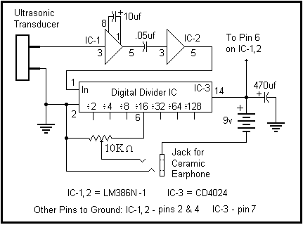
Powerful Bat Detector device Circuit Diagram

The Powerful Bat Detector is a abundance analysis blazon device. Abundance analysis blazon detectors acquiesce you to apprehend accelerated complete by digitally ascent the abundance bottomward into the animal audition range. For instance, a western pipistrelle bat emits accelerated complete in the ambit of 53 to 91 kHz. If you bisect that abundance by 16, the new abundance ambit is 3.3 to 5.7 kHz, calmly aural our audition range. Because the analysis is done digitally, all amplitude advice is lost. Accelerated sources candy by the detector catechumen to sounds like geiger-counter clicks and chirps.

The basal ambit of the Simple Bat Detector is apparent in the schematic diagram to the right. It is about composed of 3 chip circuits, or ICs. The arresting from an accelerated transducer is fed to IC-1, an LM386 audio amplifier, which is configured to accommodate a arresting accretion of 200. The arresting is accompanying to IC-2, a added LM386, by a .05 uf capacitor. IC-2 is configured to accommodate an added accretion of 20, for a absolute arrangement accretion of 4,000. The achievement of IC-2 is absolute accompanying to the ascribe of IC-3, a 7 date CMOS agenda affiliate circuit. The ascribe date of the affiliate acts as a aught bridge detector, triggering on the abrogating alteration of the arresting from IC-2. The bisect by 16 achievement is affiliated to a potentiometer, which serves as an audio akin control. A aerial impedance bowl earphone is affiliated to the achievement of the akin control. The 10K akin ascendancy is a baby printed ambit pot that is set and forgotten. The detector ambit is powered by a nine volt battery. ( The numbers abutting to the IC nodes accredit to the pin numbers of the ICs. Note the added pins listed at the basal of the schematic that charge to be angry to ground. )

A above advantage of a abundance analysis detector is that it is a advanced bandage accessory ... that agency it will let you apprehend all apparent bat sounds after the charge to tune the detector to any accurate frequency. Heterodyne detectors, which action accelerated complete in the analog domain, alone catechumen a baby ambit of frequencies at any accustomed time - you charge baddest which frequencies to accept to. If you tune up about 60 kHz to accept for a pipistrelle, you may not apprehend the big amber bats aerial nearby. The abundance analysis detector works in the agenda domain, converting the abounding spectrum of complete that the transducer is able to detect. So you get to accept to all of the accelerated sounds about you, after missing annihilation due to adverse affability choices. I feel this no-knobs-needed appropriate of the abundance analysis detector makes it a abundant best for the accidental bat observer, and student.

Read More..

Binary Coded Decimal BCD Clock

The clock circuit above uses seven ICs and 19 LEDs to indicate binary coded decimal time. The LEDs can be arranged (as shown in example above) so that each horizontal group of 3 or 4 LEDs represents a decimal digit between 0 and 9 and each individual LED represents a single bit or (binary digit) of the value. Binary digits have only two values (0 and 1) so a number written in binary would be something like 1001 or 0011, which represents decimal numbers 9 and 3 respectively. From right to left, each binary (1) represents increasing powers of 2, so that a 1 in the right hand place represents 2^0=1 and the next place to the left is 2^1=2 and then 2^2=4, and so forth.


This makes binary counting fairly easy since each digit has a value of twice the one before or 1,2,4,8,16,32,64,etc. Thus the decimal value can be found by simply adding the values of each illuminated LED in the same row, (the total is shown in the box to the right). For example, the binary number 1001 would have a decimal value of 8+0+0+1 = 9. But this is actually a binary coded decimal 9 since only values from 0 to 9 are used 0000 to 1001. A true binary clock indicating minutes of the hour would display values from 0 to 59, or 000000 to 111011. But this would be more difficult to read since adding values 32 + 16 + 8 + 2 + 1 = 59 is not as easy as 8 + 0 + 0 + 1 = 9.

The circuit is powered by a small 12.6 VAC transformer which also provides a low voltage 60 Hz signal for a very accurate time base. The transformer is connected with the secondary center tap at ground which produces about 8 volts DC across the 3300uF filter capacitor. DC power for the circuit is regulated at about 5.5 using a NPN transistor (2N3053) and 6.2 volt zener diode. The 2N3053 gets a little warm when several LEDs are on, and may require a little (top hat type) heat sink.
 
Binary Coded Decimal (BCD) Clock Circuit Diagram:


Binary-Coded-Decimal-(BCD)-Clock-Circuit-Diagram

A one second clock pulse is obtained by counting 60 cycles of the AC line signal. This is accomplished using a CMOS CD4040 12 stage binary counter (shown in light blue). The 60th count is detected by the two NAND gates connected to pins 2,3,5,and 6 of the counter. When all four of these lines are high, the count will be 60 resulting in a high level at pin 4 of the 74HC14 which resets the counter to zero and advances the seconds counter (74HC390 shown in purple) when pin 4 returns to a low state.

The same process is used to detect 60 seconds and 60 minutes to reset the counters and advance the minutes and hours counters respectively. In both of these cases the 2 and 4 bit lines of the tens counter section will be high (20+40=60). In all three cases (seconds, minutes and hours) a combination 10K resistor and 0.1uF capacitor is used at the input to the 74HC14 inverter to extend the pulse width to about 300uS so the counters will reliably reset. Without the RC parts, the reset pulse may not be long enough to reset all stages of the counter since as soon as the first bit resets, the inputs to the NAND gate will no longer all be high and the reset pulse will end. Adding the RC parts eliminates that possibility.

The reset process for the hours is a little different since for a 12 hour clock we need to reset the hours counter on the 13th count and then advance the counter one count so the display will indicate one ("1"). The 74HC00 quad NAND gate only has 4 sections with two inputs each so I used 3 diodes to detect the 13th hour (10 +1 +2 =13) which drives an inverter and also a transistor inverter (2N3904 or similar). The last 74HC14 inverter stage (pin 12 and 13) supplies a falling edge to the hours counter which advances the hours to "1" a short time after the reset pulse from the transistor inverter ends.

The pulse width from pin 12 of the inverter is a little shorter than from pin 10 which ensures that the hours clock line (pin 1 of yellow box) will move high before the end of the reset pulse form pin 10. If it were the other way around, the reset pulse may end before pin 12 of the inverter had a chance to reach a high level which would prevent the counter from advancing to "1". So it is important to use a shorter RC time at pin 13 than for the other Schmitt Trigger inputs. I used a 10K resistor and a 0.01uF cap to obtain the shorter time, but other values will work just as well. Only 2 sections of the 4071 OR gate are used, so the remaining 4 inputs (pins 8,9,12,13) should be terminated to ground if not used.

Copied Files Notice: This circuit diagram and text description has been copied and reposted without permission at: http://www.csgnetwork.com/binclockschnpl.html. The copied file has also been altered to remove the authors name and date of creation which is a clear violation of copyright law. They have also copied and modified three Java Script Calculators from this website. I have e-mailed a request to have the calculators removed and received no answer. I have also contacted the web host at Verio.net and received an autoresponse that the matter will be investigated but I doubt any action will occur. Please feel free to e-mail your opinions of plagiarism to webmaster@csgnetworks.com

Parts List:
3 - 74HC390 - Dual BCD counters
1 - CD4040 - 12 Stage Binary Counter
1 - 74HC14 - Hex Schmitt Trigger Inverter
1 - 74HC00 - Quad NAND gate
1 - CD4071 - Quad OR gate
1 - 2N3053 - NPN transistor (may need heat sink)
1 - 2N3904 - NPN transistor
3 - 1N914 - Signal diode (1N400X will also work)
2 - 1N400X - Rectifier diodes
1 - 6.2 volt - Zener diode
1 - 3300uF - Filter Capacitor - 16 volt
1 - Power Transformer - Radio Shack 273-1365A or similar
1 - 220K 1/4 or 1/8 watt resistor
1 - 150 ohm 1/4 watt resistor
19 - 220 ohm 1/4 or 1/8 watt resistors
11 - 10K 1/4 or 1/8 watt resistors
2 - 0.01uF capacitors
4 - 0.1uF capacitors
19 - Red LEDs (15 mA)
2 - Momentary push button switches (to set the time)
1 - Toggle switch (to start the clock at a precise time)
Read More..

Electric Motor Repair

Electrical engines are a significant aspect of most large functions. They are used to make current that can be linked with a strength or to immediately petrol other systems. These engines are complicated items of professional systems and consequently it is not recommended for a individual who is not a certified fix individual to attempt to fix them. This transforms digital strength into technical strength.

They come in a wide range of types and the type that you use will depend on what you need it for. The primary parts are the blades and the stator. The blades is the going aspect and the stator is the invitations aspect of it. These two items make the time frame for it.

Most engines are attractive in characteristics. Both the blades and the stator generate a attractive area which makes a twisting, or demand on the powerplant base and makes the revolving of the powerplant. This is how it functions.

Finding a reliable serviceman for your powerplant can be a complicated procedure. The crucial aspect is making sure that the serviceman you seek the services of is certified in mending. An search can help you discover certified serviceman in your community that can fulfill your immediate and continuing needs.

Once youve found the serviceman or fix company youd like to use, you should have them come and visit the site as soon as possible to analyze it. Once the serviceman has analyzed the position of your powerplant unit, he can give you an calculate regarding the money of the fix.

The fix is the first step in a long procedure of its servicing. Once it has been fixed, youre going to want to set up a frequent servicing routine in order to reduce the cost and agony of upcoming fixes. Maintenance is the single greatest factor you can do to reduce the need for fixes.

The best factor you can do with regards to fix is to put the extra persistence in to make sure that frequent servicing is being done. Effectively managed engines need less fix and cause less problems for you. If you can keep your engines properly managed youre less likely to need comprehensive and expensive fixes.

Electric powerplant fix can take many types, based on what type of powerplant unit you have and the characteristics of its use in your business. The best factor you can do with your damaged powerplant unit is to discover and seek the services of a reliable serviceman to do the fixes. Electrical powerplant fix can be reduced by exercising servicing on your powerplant unit.
Read More..

Thursday, November 21, 2013

Simple Remote Control Tester

Nearly always when a remote control doesn’t work, the underlying problem is elementary: the unit does not emit light. The cause may be dry solder joints, defective LEDs etc., but also a flat battery (perhaps due to stuck key). The human eye is unable to perceive infra-red light. By contrast, an ordinary photo transistor like the BP103 has no problems working in the infrared spectrum, so in the circuit here it simply biases the BC558 which, in turn, makes LED D1 flash in sympathy with the telegram from the remote control. The preset in the circuit determines the sensitivity.

Simple Remote Control Tester
source : Simple Remote Control Tester

Read More..

Simple Source Voltage Protector

Simple Source Voltage Protector
Protection of electronic devices with a DC voltage source of voltage source obligatory reversal, especially protection of the source voltage is reversed. The definition of "Protectors Voltage Sources" in this article are the source voltage surge protector circuit which serves to protect the device from the reversal of the voltage source to the appliance electronics.

Source voltage surge protector will expressed in this article are general, so that later in their applications to stay adjusted value of the component with the voltage source needs an electronic appliance. Let us start reviewing Protectors Voltage Source by simple and modest.

Source voltage protection with 1 diode


Diodes are used as a protector of the source voltage installation tebaliknya voltage source is installed in series with the input line voltage source electronics devices. Installation of surge protector diode as a voltage source is on the positive line voltage source input device. The function is to drain diode current (voltage source) in one direction only, so that in the event of an upside-down voltage source. then the voltage source is not in the channel (in blocks) to the device. The value of the diode is tailored to the needs of the source voltage of the device itself.

Source voltage protection with dioda bridge


Protectors voltage source with a diode bridge in principle the same as the surge protector with a voltage source diode 1 pc. The difference is the source voltage surge protector is not blocking the source voltage, but the source voltage surge protector is to reverse the flow of the source voltage of one polarity in the case of voltage source. From the picture above to explain the purpose of reversing the voltage source in question, namely when given a source voltage through a voltage surge protector is the source of positive polarity (+) will be directly in the stream leading to the positive input line of tools and the source of negative voltage (-) will be directed to the negative voltage source input line tool.
Read More..

Pieces Parts Components and Sound

If you are in the market for a surround sound system Im sure you are trying to learn as much as possible about options before you reach the buying stage. One thing to keep in mind is that there are many options and most of them will come down to a matter of taste when all is said and done. There is no right or wrong component or process when it comes to buying a surround sound system only what does and doesnt work for you and the space you have available.

You will find throughout the process that there are many parts, pieces, and components that you may purchase for your surround sound system and even more prices for those individual items. Ultimately the decision comes down to how much of a sound snob you are. Seriously. I must admit that my personal preference is for the most possible sound saturation and the most realistic possible sound as possible. For this reason I am more interested in buying the components as individuals rather than a simple AV receiver. This does not mean that an AV receiver wouldnt be perfectly adequate (especially in relation to the size of my rather small media room) but that I prefer the added control over the sound that individual components provides.

Unfortunately, I cannot tell you which will work best for your situation as your tastes and requirements will also play heavily on which decision is best for you as will your budget. Some people do not place nearly as much emphasis on sound as I do and most people have budget constraints that make individual components seem like a bit of overkill. However, if you spend, as much time as I do submersing yourself in experiences that require sound, then you will find that the investment in these components may be well worth every penny. You will pay a few though and should understand that now.

If you want to build a fabulous surround sound system you will need to start with the preamp or processor. This will be the heart of your sound system and works as a surround processor, AM/FM radio, amplifier, and preamp in one. This piece of equipment receives the signals and then sends them on their merry way. Amazingly enough the information always seems to find its way where it should go-assuming of course that everything is plugged into its proper channel.

The tuner allows you to receive and process AM/FM radio signals, XM or Satellite Radio, and some High Definition signals as well. The amplifier adds power to the sound or as its name implies, amplifies it. This allows the sound to reach across the room so that everyone in the room is touched by it.  

These components each achieve functions individually that a good quality AV receiver can accomplish. The difference is always in degrees and depth. The AV receiver allows some of the functionality of each but doesnt quite match the control and nuances that can be achieved with any one of the pieces individually. The average consumer doesnt need that sizeable of an investment in equipment, money, time, or space in order to achieve excellent theater quality sound in their home theater system and that is the important thing to remember. 

If you are hoping to imitate a theater experience in an average size room, chances are you will never need anything more than a decent AV receiver and an excellent set of speakers. The more speakers you have in your surround sound system, the better the quality of the sound will be. However, better quality speakers will trump marginal quality equipment any day while marginal quality speakers can still ruin the sound of even the best quality AV equipment. The best advice I can give you when purchasing equipment for your surround sound system is to make sure you put your money in your speakers and sort the rest out afterwards.

PPPPP

664

Read More..

Traffic Light 20 Chanel based on 74LSxx

Traffic Light 20 Chanel based on 74LSxxTraffic Light 20 Chanel based on 74LSxx


This view of the proposed traffic Light 20 Chane based only on family and 74LSxx IC 555 as clock source. It is a digital logic circuit. To construct the traffic light rangkaian Control requires no programming of microcontrollers.


This page features a circuit that has twenty open collector outputs that turn on one at a time in a continuous sequence. The circuit make use of the family 74LSxx TTL integrated logic devices. The circuits are designed to drive light emitting diodes or low current and low voltage incandescent lamps, but can also lead to other charges of 80 milliamps.


notes:

  • The low output go in sequence from 1 - 0 and back to 1 -0

  • At the clock rate of the 555 timer
  • c3 = 1uf to 10uf depending on the rate of change desured
  • R2 (Variable resistor) in use to determine the timer
Read More..

Wednesday, November 20, 2013

Amplifier Circuit with IC AN7133

 *note:this is stereo amplifier
 
This circuit is stereo power amplifier . Voltage input or Supply voltage with dual voltage minimum 6 volt , and maximum 18 volt . You cant  use triple voltage in this amplifier and must DC voltage not AC voltage . Maximum output power 2 X 15 watt  with minimum impedance 4 ohm . You can use this amplifier on car commonly called car amplifier, on Personal Computer (PC) , on small room , etc.

See this schematic amplifier circuit with IC AN7133 below :


Read More..

Schematic Audio Power Amplifier with IC TDA2822

TDA2822 is manufactered by PHILIPS , its based on this amplifier . Minimum voltage 3 volts and maximum voltage 15 volts. Power output 2 x 1,8 stereo with 4 Ohm impedance. Quiescent current 6 mA , sensitive input is 30 Hz to 18 kHz. See circuit diagram below :

Read More..

Automatic Light Controller Using 7806

Voltage
regulator ICs (78xx series) provide a steady output voltage, as
against a widely fluctuating input supply, when the common terminal is
grounded. Any voltage about zero volt (ground) connected in the common
terminal is added to the output voltage. That means the increase in the
common terminal voltage is reflected at the output. On the other hand,
if the common terminal is disconnected from the ground, the full input
voltage is available at the output. This characteristic is utilised in
the present circuit.

When the common terminal is connected to
the ground,the regulator output is equivalent to the rated voltage, and
as soon as the terminal is disconnected from the ground, the output
increases up to the input voltage. The common terminal is controlled by a
transistor, which works as a switch on the terminal. For automatic
control of light, a light-dependent resistor (LDR1) is connected to the
base of the transistor. In this way, the voltage regulator is able to
operate a light bulb automatically as per the ambient light.

To
derive the power supply for the circuit, the 50Hz, 230V AC mains is
stepped down by transformer X1 to deliver a secondary output of 12V, 250
mA. The secondary output of the transformer is applied to a bridge
rectifier comprising diodes D1 through D4, filtered by capacitor C1 and
fed to the input terminal of the regulator (IC1). The common terminal
(pin 2) of IC1 is connected to the ground line of the circuit through
transistor BC557 (T1). The transistor is biased by R2, R3, VR1 and LDR1.


Automatic Light Controller Using 7806 circuit schematic

The
grounding of IC1 is controlled by transistor T1, while light is sensed
by LDR1. Using preset VR1, you can adjust the light-sensing level of
transistor T1. The output of IC1 is fed to the base of transistor T2
(through resistor R4 and zener diode ZD1) and relay RL1. LED1 connected
across the positive and ground supply lines acts as a power-‘on’
indicator. Normally, the resistance of LDR1 is low during daytime and
high during nighttime. During daytime, when light falls on LDR1, pnp
transistor T1 conducts.

The common terminal of IC1 connects to
the ground and IC1 outputs 6V. As a result, transistor T2 does not
conduct and the relay remains de-energised. The light bulb remains ‘off’
as the mains connection is not completed through the relay contacts.
During nighttime, when no light falls on LDR1, it offers a high
resistance at the base junction of transistor T1. So the bias is greatly
reduced and T1 doesn’t conduct. Effectively, this removes the common
terminal of IC1 from ground and it directs the full input DC to the
output. Transistor T2 conducts and the relay energises to light up the
bulb as mains connection completes through the relay contacts.

As
LDR1 is in parallel to VR1 R3 combination, it effectively applies only
half of the total resistance of the network formed by R3, VR1 and LDR1
to the junction at T1 in total darkness. In bright light, it greatly
reduces the total effective resistance at the junction. The circui t is
simple and can be assembled on a small general-purpose PCB. Use a
heat-sink for IC1. Make sure that LDR1 and the light bulb are well
separated. The circuit can be used for streetlights, tubelights or any
other home electrical lighting system that needs to be automated.
Read More..

The Importance of a Good Auto Sound System

If you spend a good deal of time in you car, and yes, the morning commute to work and the evening commute home each and every day definitely counts, you are probably more than slightly aware of the benefits of having a good auto sound system. Your sound system is your companion in your travels most of the time. Even those who have children often spend a great deal of time driving alone.


The Importance of a Good Auto Sound SystemFor those long and sometimes lonely miles your auto sound system is the voice of reason, the energetic beat, and the information that keeps you up on current events, weather forecasts, and what is going on in the world of the rich and famous. Even if you arent all that into music there is the wide and wonderful world of talk radio that keeps many of us informed and inflamed about issues that are important to us and causes which we feel passionately about.

The proper auto sound system affects the way we hear everything that comes through our radios. It doesnt really matter if you have the latest and greatest of subscription programs, XML programming, or even digital radio if your sound system is poor the quality of your programming will never reach your ears. Your sound system is the difference in standard sounds coming through your speakers and excellence making its way to your ears.

Contrary to popular belief however, you do not have to have the loudest sound system in order to have the best sound system. The truth of the matter is that once the music is so loud it ceases to sound like music and comes across to those inside and outside of your automobile more as noise than the wonderful music it may be in other circumstances. While there are many who enjoy the throbbing and jumping sounds that come from over emphasized bass, there is something to be said for an auto sound system that is well rounded and balanced. A good sound system will make all aspects of the music sound better and not just a certain few.

The important thing about sound systems arent the price that they command, the bass that they flaunt, or even the most minute details of the making and manufacturing of the sound system. The true beauty of a sound system lies in the fact that it should be music to your ears. You and you alone can choose the sound system that you like best as every person has different things they will listen for and enjoy in not only their music but also their sound systems. I love many different types of music and as a result will tend to listen to several different music genres as well as a stint of talk radio on several different systems and elect the one that sounds the best on the most of the music platforms and genres I prefer. I recommend a course of action similar to this to all who are interested in purchasing an auto sound system for their vehicle.

One thing that often gets overlooked is how much time we really spend in our vehicles in the course of a week. Most people pay very little time, money, or attention the particular stereos we put into our vehicles when in reality we spend nearly as much time each week listening to our auto sound systems as we do watching the televisions in our home. Music is all around us and it deeply affects and enhances our joys, our sorrows, even our romance. For those reasons, shouldnt we invest as much, if not more, time and energy in a great auto sound system as we do in a television for our homes?

By taking the time to get the perfect sound system for our vehicles when we first purchase our automobiles we will enjoy the maximum benefit our sound systems can provide. By enjoying our sound system, more people are willing to hang on to their vehicles longer which actually saves a great deal of money in the long run while also increasing your overall enjoyment of your time spent commuting to and from work each and every day.

Read More..

Tuesday, November 19, 2013

14W Class A Amplifier Circuit with 2N3055

14W Class A Amplifier Circuit with 2N305514W Class A Amplifier Circuit with 2N3055


This class A amplifier circuit requires a preamp as it hasnt got much gain. Requires large heat sinks and a large transformer and a source of great power and wiring carefully, but the end is very simple and sounds great. The zener diode disclaims any wave from the power supply, but still just want a wave of 10mV max. The ripples reaching the entrance is amplified, so the zener get rid of that, but there is still dominated him to reach the power stage.


Many early amplifiers operated in Class A, but as 10W power output rose above the problems of heat dissipation and design of the power supply caused most manufacturers to turn to the simplest, arrangements more efficient class B and put up with the consequent decrease in the perceived quality of output. Why Class? Because, when biased in class A, the transistors are always on, always ready to respond instantly to an input signal. Class B and Class AB output stage requires a microsecond or more on. The kind of a cleaner operation allows operation under high voltage swing that occurs when the transient audio signal feed difficult loads. Your amplifier is basically simple, as shown in the block diagram.
Read More..

555 timer chip tester

555 timer chip tester
IC 555 timer tester is a simple circuit that serves to test the condition of IC 555. 555 timer circuit tester, in principle, start the timer 555 in astable multivibrator mode. As an indicator of the status of the timer 555 good condition or damaged to use 2 pieces LED which will light up in a blink alternately when the timer 555 in good condition. 

And only one will turn on or off all the timer 555 when the condition is broken. 555 timer circuit tester is powered using 9 Volt DC voltage source. Complete circuit tester 555 as follows.

tester schematic circuit 55
Tester schematic
How to use 555 timer tester is in conjuction with IC 555 to test the existing IC socket according to the orderbutton. Then activate the power switch to begin testing the 555 timer ic. Then live we observe the LED indicators 2buah before, whether flashing alternately (good) or not blink or even die all (timer 555 damaged).
Read More..