Showing posts with label audio. Show all posts

Friday, October 24, 2014

5 Watt Class A Audio Amplifier Circuit diagram

This solid-state push-pull single-ended Class A circuit is capable of providing a sound comparable to those valve amplifiers, delivering more output power (6.9W measured across a 8 Ohm loudspeaker cabinet load), less THD, higher input sensitivity and better linearity. Voltage and current required for this circuit are 24V and 700mA respectively, compared to 250V HT rail and 1A @ 6.3V filament heating for valve-operated amplifiers. The only penalty for the transistor operated circuit is the necessity of using a rather large Heatsink for Q2 and Q3 (compared to the maximum power delivered).In any case, the amount of heat generated by this circuit can be comparable to that of a one-valve amplifier. An optional bass-boost facility can be added, by means of R5 and C5.

 Circuit diagram:

5 Watt Class-A Audio Amplifier Circuit Diagram


Parts:

P1 = 47K
R1 = 100K
R2 = 12K
R3 = 47K
R4 = 8.2K
R5 = 1.5K
R6 = 2.7K
R7 = 100R
R8 = 100R
R9 = 560R-1/2W
R10 = 1R-1/2W
Q1 = BC560
Q2 = BD439
Q3 = BD439
C1 = 10uF-63V
C2 = 10uF-63V
C3 = 47uF-25V
C4 = 100uF-35V
C5 = 150nF-63V
C6 = 220uF-25V
C7 = 220uF-25V
C8 = 1000uF-25V
SPKR = 5W-8R Speaker

Notes:
  • If necessary, R2 can be adjusted to obtain 13V across C8 positive lead and negative ground.
  • Total current drawing of the circuit, best measured by inserting the probes of an Avo-meter across the positive output of the power supply and the positive rail input of the amplifier, must be 700mA. Adjust R8 to obtain this value if necessary.
  • Q2 and Q3 must be mounted on a finned Heatsink of 120x50x25mm. Minimum dimensions.
  • Add R5 and C5 if the bass-boost facility is required.
Read More..

Monday, October 20, 2014

Quality Stereo Wireless Microphone or Audio Link

Quality Stereo Wireless Microphone or Audio Link. This stereo FM wireless microphone also makes a great quality audio link. We tested it to beyond 50 meters and it was rock solid. It’s certainly not the first wireless microphone we’ve ever published but this one is a little different. It’s stereo, providing surprisingly good quality sound. Second, it has a really good range. We tested it at well over 50m and it was still performing very well – noise-free, in fact – but at the time we couldn’t get our receiver any further away. So it’s likely to have even better range than that.

main-quality-stereo-wireless-microphone-or-audio-link-circuit

Complete Project:
quality-stereo-wireless-microphone-or-audio-link quality-stereo-wireless-microphone-or-audio-link-circuit

Its easy to build, requires very little setup... and its cheap! In fact, the low price might turn some people off, thinking its low quality. Try it - and be pleasantly surprised!

quality-stereo-wireless-microphone-or-audio-link-front

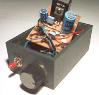
Third, it really is simple to build – the hard work (the transmitter module) is already done for you. It’s just a matter of assembling the microphone module, which contains the electret mics themselves, preamp and level controls, and soldering the transmitter module onto it, "piggy back" style.

FM Transmitter:

Finally, the transmitter module is crystal-locked, so you won’t have the drift probles of some earlier wireless microphones. And just in case you were wondering, that doesn’t mean the output is locked to one particular frequency – it has a nifty synthesis circuit built in to give you the choice of seven different frequencies between 106.7MHz and 107.7MHz.
On-board preset pots adjust the sensitivity of each channel to take into account mic differences or if you require different levels in each channel.

fm-transmitter-module-top-side-view

By the way, the transmitter module is quite capable of operating at line level if you want just a line level transmitter (eg, to feed an audio program around your home). Sensitivity is about 100mV. Oatley Electronics, who designed the kit, have the transmitter module available by itself if that’s what you’re after. But more on that anon.

fm-transmitter-module-bottom-side-view

Parts Layout:
parts-layout-quality-audio-link-circuit-diagram
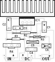
parts-layout-of-quality-stereo-wireless-microphone-or-audio-link

You also have the choice of two power supply levels – 3-6V or 7-15V DC. The latter results in a lower current drain. The transmitter module also has a "5V out" rail to supply power to the preamp module.

Quality Stereo Wireless Microphone Circuit Diagram:
quality-stereo-wireless-microphone-or-audio-link-circuit-diagram

Two electret microphone inserts are supplied in the kit. These can be soldered direct to the PC board to make it a fully self-contained project or they can be attached to the board via suitable lengths of mini shielded coax cable. A third option is to use "proper" microphones – they can be electret or dynamic types – but no provision has been made for plugging these in.

Typical Specs:
Audio response:.....................20Hz-15kHz.
Channel separation: ........................40dB
Total Harmonic Distortion: ...............0.1%
Output Frequency:...........106.7-107.2MHz
Pre Emphasis: ..................................50μS
DC supply voltage range: ................3-15V
Supply Current: .......................30mA @ 9V
Read More..

10W Small Audio Amplifier

You can use this powerfull amplifier in any small audio project. It is very small (6.5 x 4.5 cm).It outputs 10W and uses a 9V battery.

10W Small Audio Amplifier


10W Small Audio Amplifier
Component


 10W Small Audio Amplifier
PCB


Componets List
R1 : 6 Ohm
R2 : 220 Ohm
R3 : nothing
R4 : 10 KOhm pontesiometer
C1 : 2200 uF / 25V
C2 : 470 uF / 16V
C3 : 470 nF / 63V
C4 : 100 nF
C5 : nothing
C6 : nothing
IC1 : TDA 2003


Read More..

USB Powered Audio Power Amplifier Circuit Diagram

This USB Powered Audio Power Amplifier Circuit Diagram of multimedia speakers for PCs has single-chip-based design, low-voltage power supply, compatibility with USB power, easy heat-sinking, low cost, high flexibility and wide temperature tolerance. At the heart of the circuit is IC TDA2822M. This IC is, in fact, mono-lithic type in 8-lead mini DIP package. It is intended for use as a dual audio power amplifier in battery-powered sound players. Specs of TDA2822M are low quiescent current, low crossover distortion, supply voltage down to 1.8 volts and minimum output power of around 450 mW/channel with 4-ohm loudspeaker at 5V DC supply input. 

An ideal power amplifier can be simply defined as a circuit that can deliver audio power into external loads without generating significant signal distortion and without consuming excessive quiescent current. This circuit is powered by 5V DC supply available from the USB port of the PC. When power switch S1 is flipped to ‘on’ position, 5V power supply is extended to the circuit and power-indicator red LED1 lights up instantly. Resistor R1 is a current surge limiter and capacitors C1 and C4 act as buffers. Working of the circuit is simple. Audio signals from the PC audio socket/headphone socket are fed to the amplifier circuit through components R2 and C2 (left channel), and R3 and C3 (right channel).

Circuit diagram:
USB Powered Audio Power Amplifier Circuit Diagram

Potmeter VR1 works as the volume controller for left (L) channel and potmeter VR2 works for right (R) channel. Pin 7 of TDA2822M receives the left-channel sound signals and pin 6 receives the right-channel signals through VR1 and VR2, respectively. Ampl i f ied signals for driving the left and right loudspeakers are available at pins 1 and 3 of IC1, respectively. Components R5 and C8, and R6 and C10 form the traditional zobel network. Assemble the circuit on a medium-size, general-purpose PCB and enclose in a suitable cabinet. It is advisable to use a socket for IC TDA2822M. The external connections should be made using suitably screened wires for better result.
Read More..

Friday, September 26, 2014

Simple Automatic Switch For Audio Power Amplifier

Simple Automatic Switch For Audio Power Amplifier.Circuit of an automatic switch for audio power amplifier stage is presented here. The circuit uses stereo preamplifier output to detect the presence of audio to switch the audio power amplifier on only when audio is present. The circuit thus helps curtail power wastage. IC1 is used as an inverting adder. The input signals from left and right channels are combined to form a common signal for IC2, which is used as an open loop comparator. IC3 (NE556) is a dual timer. Its second section, i.e., IC3(b), is configured as monostable multivibrator. Output of IC3(b) is used to switch the power amplifier on or off through a Darlington pair formed by transistors T1 and T2. IC3(a) is used to trigger the monostable multivibrator whenever an input signal is sensed.
Circuit diagram:
Automatic Switch For Audio Power Amplifier-Circuit-Diagram
Automatic Switch For Audio Power Amplifier Circuit Diagram

Under ‘no signal’ condition, pin 3 of IC2 is negative with respect to its pin 2. Hence the output of IC2 is low and as a result output of IC3(a) is high. Since there is no trigger at pin 8 of IC3(b), the output of IC3(b) will be low and the amplifier will be off. When an input singal is applied to IC1, IC2 converts the inverted sum of the input signals into a rectangular waveform by comparing it with a constant voltage which can be controlled by varying potentiometer VR1. When the output of IC2 is high, output pin 5 of IC3 goes low, thus triggering the monostable multivibrator. As soon as the audio input to IC1 stops, pin 5 of IC3 goes high and pin 1 of IC3 discharges through capacitor C3, thus resetting the monostable multivibrator. 

Hence, as long as input signals are applied, the amplifier remains ‘on.’ When the input signals are removed, i.e., when signal level is zero, the amplifier switches off after the mono flip-flop delay period determined by the values of resistor R8 and capacitor C3. If no input signals are sensed within this time, the amplifier turns off—else it remains on. Power supply for the circuit can be obtained from the power supply of the amplifier. Hence, the circuit can be permanently fitted in the amplifier box itself. The main switch of the amplifier should be always kept on. Resistors R1 and R2 are used to divide single voltage supply into two equal parts.

Capacitors C1 and C2 are used as regulators and also as an AC bypass for input signals. Diode D1 is used so that loading fluctuations in power amplifier do not affect circuit regulation. Transisitor T2 acts as a high voltage switch which may be replaced by any other high voltage switching transistor satisfying amplifier current requirements. Value of resistor R10 should be modified for large current requirement. The LED glows when the amplifier is on. The circuit is very useful and relieves one from putting the amplifier on and off every time one plays a cassette or radio etc. 
Read More..

Sunday, February 9, 2014

Stereo High Power Audio Amplifier

Stereo High Power Audio Amplifier

This is a stereo amplifier circuit which has a high output power and excellent sound quality. Amplifier circuit has a very high gain output stage resulting in the deterioration of signal noise distance. This amplifier circuit having an output power of more than 400 Watt x 2 (Stereo) with the speaker impedance 4 Ohm - 8 Ohm. Power supply voltage circuit to supply this high power amplifier with maximum - + 75 Volt DC. Heres the scheme of High Power Amplifier :

High Power Amplifier Circuit Diagram


Read More..

Saturday, February 8, 2014

Car audio amplifier using TDA2003 IC

Car audio amplifier using TDA2003 IC

Easy low power car audio amplifier circuit on TDA 2003. The circuit is Easy to construct. TDA2003 is an integrated radio amplifier from ST Micro electronics that like short circuit protection for all pins, thermal over low harmonic distortion, low cross over distortion etc. In the circuit given here TDA2003 is wired as a mono amplifier operating from a 12V .


Resistors R2 and R3 forms a feedback network that sets the amplifiers gain. C7 input DC de-coupling capacitor and C5 couples the speaker to the amplifiers output. C4 } for improving the ripple rejection C1 and C2 are employed for power filtering. C3 and R1 are used for setting the frequency cut-off. Network comprising of C6 and R4 for frequency stabilization and oscillation.

Notes.

  • Assemble the circuit on a good quality PCB.
  • Heat sinks are necessary for both ICs.
  • The circuit can be operated from 12V DC.
  • S1 is the ON/OFF switch.
Read More..

Audio Controlled Mains Switch

It is often useful for audio or video equipment to be switched off automatically after there has been no input signal for a while. The function of the on-off switch in such equipment is then taken over by switch S2 in the accompanying diagram. It remains, however, possible to  switch off manually by means of Si. Automatic  switch-off occurs after there has been no input  signal for about 2 minutes: this delay makes it possible for a new record or cassette to be placed in the  relevant machine.
 
The audio input to the proposed circuit may be  taken from the output of the relevant TV set, amplifier, or whatever. The input earth is held at + 6 V  with respect to the circuit earth by potential divider  Ri-R2-R3-R4. The two 741s function as comparators: the output of ICi goes high when the in- put signal is greater than + 50 mV, whereas the out- put of IC2 goes high when the input signal  becomes more negative than -50 mV. Resistors  R6, R7, and R8 form an OR gate that drives transistor Ti. If the output of either ICi or IC2 is logic  1, Ti conducts.
 
Circuit diagram :
Audio-Controlled-Mains-Switch-Circuit-Diagram
Audio Controlled Mains Switch Circuit Diagram

The 555  operates as a retrigger able monostable,  whose period is determined by Rio and Ci. The  device is triggered when its pin 2 is earthed by the  closing of S2. Its output, pin 3, then remains high  for 1 to 2 minutes, depending on the leakage cur- rent of the 555. 

The monostable resets itself as soon  as the potential across Ci exceeds a certain value.  As long as there is an input signal to the circuit, Ti conducts and Ci remains uncharged. As soon as  the audio signal ceases, Ti switches off, and Ci  charges until the potential across it is sufficient to  reset the 555. The monostable may also be reset by  closing Si, which connects pin 6 of the 555 to + 12 V.
 
Audio-Controlled-Mains-Switch
When IC3 is reset, Ci is discharged via its pin 7. Resistor Rrn serves as protection, because without it Ti could short-circuit the supply lines. When the output of IC3 goes high, T2 conducts,  the relay is energized, and the relay contacts switch on the mains voltage as appropriate. To counter the induced potential when the relay contacts close, which could damage T2, diode Di has been connected in parallel with the relay coil. 


http://www.ecircuitslab.com
Read More..

Friday, February 7, 2014

Stereo TDA2822 audio power amplifier circuit

Stereo TDA2822 audio amplifier circuit
In this series I use IC tda2822M as the main amplifier, but if you want to use in addition to IC TDA2822M you can use ic I mentioned this is KA2209, NJM2073, U2822B, U2823B. Output is issued no more than 4W, which had low output. Supply voltage from 3 volts to 16 volts.


Below its schematics of TDA2822 stereo audio power amplifier

TDA2822 amplifier schematics

Part description
R1 = 4.7R
R2 = 4.7R
C1 = 1uF
C2 = 100uF
C3 = 100uF
C4 = 0.1uF
C5 = 470uF
C6 = 1uF
C7 = 100uF
C8 = 0.1uF
C9 = 470uF
ICs = KA2209 , NJM2073 , TDA2822 , U2822B , U2823B
Read More..

Wednesday, February 5, 2014

Schematic Audio Power Amplifier with IC AN7105

This Schematic Circuit Audio Amplifier use IC AN7105 , minimum voltage 1,5 volt and maximum voltage 9,5 volt. This is a low voltage Amplifier , with output speaker stereo 2 X 0,38 watt . Its so low power amplifier. Impedance speaker is 32 Ohm ,with Frequency 20 Hz -20 kHz.

See this Circuit and package IC AN7105 below :


Package IC is DIP-18

Click to view Enlarge


Read More..

Monday, January 13, 2014

5 8 Watt audio power amplifier

5,8watt amplifier schematics
This amplifier circuit has a power output of a small or too low at 5.8 Watt, which uses IC KA2205. The required voltage for at least 6 volts to 18 volts DC maximum.


Schematics power audio amplifier with IC KA2205

low power amplifier
Component List
C1 = 1uF
C2 = 100uF
C3 = 47uF
C4 = 1000uF
C5 = 0.1uF
C6 = 220uF
IC1 = KA2205

Read More..

Wednesday, December 25, 2013

1 6 Watt intregated circuit audio amplifier

This Circut based on IC TDA7231 , Minimum voltage require 2 Volts and maximum voltage 15 volts . I recomended voltage is 12 volt DC. Power output 1,6 Watt with 4 Ohm impedance. See audio amplifier with IC TDA7231 below :
Read More..

Tuesday, December 17, 2013

Subowoofer audio car amplifier

For the a one amplifier circuit is very suitable for use in applications subwoofer speaker, which allows for higher spending enough bass. Although output was spent not high, but for bass sounds do not undoubtedly. Indeed, the output is only 20W mono amplifier with 8 ohm impedance. With a maximum supply 44Volt DC.
car subwoofer
Part list
R1 = 47R
R2 = 100K
R3 = 1R 2W
C1 = 2.2uF
C2 = 220uF
C3 = 100uF
C4 = 47uF
C5 = 68uF
C6 = 100uF
C7 = 1000uF
C8 = 0.1uF
U1 = STK024 , STK031 ,STK035
Read More..

Monday, December 16, 2013

Schematic Audio Power Amplifier with IC AN7118S

 *notif : this circuit is stereo power amplifier

Although the schematic power amplifier with IC AN7118S is difficult for lees understood making of  PCB track . But once tried to design on PCB is not so difficult. Because the actual components close together and easy to design it. This Circuit need minimum voltage 1 volt and  maximum voltage 3 volt. It is a low voltage amplifier with power output 2 x 35 m Watt .

Schematic circuit below :


Click to Enlarge

Components Required :

Resistor / Condensator / Capacitor : 4,7Ohm (2x) , 0,01 uF (2x) , 47uf (2x) , 68 pf (2x) , 1uF (2x) ,  22uF (2x) , 220 uF (1x) , 470uf (2x). Condensator / capacitor voltage use 16 volt. Only Condensator on output speaker use voltage 25 volt.

Read More..

Wednesday, December 11, 2013

TA7214 stereo audio power amplifier

Not all that omplicated circuit schematic of power amplifiers have a good and quality sound, but in the circuit above , although a little tricky for the layman on the circuit , and the sound quality is also good.
Technical information :
V max  = 16 Vdc
V min  = 10 Vdc
P out    = 2 x 9,6W
R l       = 4 Ohm
Read More..

Thursday, December 5, 2013

20W Surround audio amplifier with SI 1020G

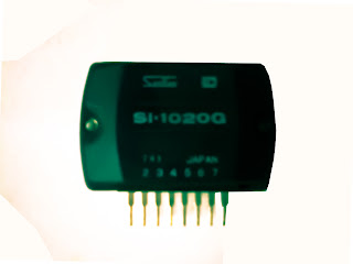
IC amplifier surroundHave you been use the IC above? if those who have not, IC above is used or applied to the audio power amplifier. IC processing is quite good for use on amplifier home, or room. IC used is SI1020G who have not very high output with only 20W 8 ohm impedance speakers. Supply voltage ranging from 12 volt to 23 volts.


Below schematic audio amplifier with IC SI1020G
surround audio amplifier
Part List
R1 = 100K
R2 = 1R
C1 = 2u2F
C2 = 100uF
C3 = 47uF
C4 = 10uF
C5 = 2200uF
C6 = 47uF
C7 = 100uF 
Read More..

Saturday, November 30, 2013

Subowoofer audio car amplifier

For the a one amplifier circuit is very suitable for use in applications subwoofer speaker, which allows for higher spending enough bass. Although output was spent not high, but for bass sounds do not undoubtedly. Indeed, the output is only 20W mono amplifier with 8 ohm impedance. With a maximum supply 44Volt DC.
car subwoofer
Part list
R1 = 47R
R2 = 100K
R3 = 1R 2W
C1 = 2.2uF
C2 = 220uF
C3 = 100uF
C4 = 47uF
C5 = 68uF
C6 = 100uF
C7 = 1000uF
C8 = 0.1uF
U1 = STK024 , STK031 ,STK035
Read More..

Wednesday, November 20, 2013

Schematic Audio Power Amplifier with IC TDA2822

TDA2822 is manufactered by PHILIPS , its based on this amplifier . Minimum voltage 3 volts and maximum voltage 15 volts. Power output 2 x 1,8 stereo with 4 Ohm impedance. Quiescent current 6 mA , sensitive input is 30 Hz to 18 kHz. See circuit diagram below :

Read More..

Monday, November 18, 2013

Audio peak indicator circuit

Audio peak indicator circuit
The existence of the peak indicator (Audio Peak Indicator) in an audio device is needed. Audio Peak indicator is a simple circuit to detect the peak level of audio signal. Audio Peak indicator circuit is built with duabuah transistor and LED indicator as peak level detection of audio signals. 


The main function of a series of Audio Peak indicator is to determine the occurrence of the peak level of audio signal which is more than +4 dB, equivalent to 1.25 V rms. If the received audio signal Audio Peak Indicator more than +4 dB was the LEDs in series Peak Audio This indicator will light. Audio Peak indicator circuit is mounted on the output audio system.

audio peak indicator schematics
Audio peak indicator
Audio Peak Indicator Component List:
R1 = 10Kohm
R2 = 1.2Kohm
R3 = 220Kohm
R4 = 4.7Kohm
R5 = 4.7Kohm
C1 = 47uF 25V
C2 = 2.2uF 25V
Q1 = BC550C
Q2 = BC550C
D1 = Red Led
Read More..

Sunday, November 17, 2013

LED Audio Level Meter Circuit

This circuit uses two quad op-amps to form an eight LED audio level meter. The op-amp used in this particular circuit is the LM324. It is a popular IC and should be available from many parts stores.

LED audio level meter
LED audio level meter schematic
The 1K resistors in the circuit are essential so that the LEDs turn on at different audio levels. There is no reason why you cant change these resistors, although anything above 5K may cause some of the LEDs to never switch on. This circuit is easily expandable with more op-amps, and is not limited to use with the LM324. Pretty much any op-amp will work as long as you look up the pinouts and make sure everything is properly connected.

The 33K resistor on the schematic is to keep the signal input to the circuit at a low level. It is unlikely you will find a 33K resistor, so the closest you can get should do. The value of this resistor may need to be changed, so it is best you breadboard this circuit before actually constructing it on PCB. The circuit in its current form will accept line level inputs from sources such as the aux out on a Hi-Fi, all though could be easily modified to accept speaker inputs.

The audio + is connected to the main positive rail, while the audio - is used for signal input. The 50k pot can be used to vary the sensitivity of the circuit.
Read More..