Showing posts with label car. Show all posts

Monday, October 20, 2014

Car Charger And Switcher Circuit For SLA Battery

This circuit was devised to switch power to a Peltier cooler in a vehicle. Power to the load from the vehicle’s battery is switched by a SPDT relay while the ignition switch is turned on and from the SLA auxiliary battery when the ignition is off.

The SLA battery is charged from the vehicle’s battery. When the engine is running, the voltage remains fairly constant, which greatly simplifies the charging circuit. If the SLA battery is fully charged, any further charging current from the vehicle battery is limited by a 3.3W 5W resistor (R1). If the SLA battery is deeply discharged, the voltage drop across this resistor will be enough to bias on PNP transistor Q1. This will turn on P-channel Mosfet Q2 and it will provide further charging current via R2, effectively becoming a 2-step charger.

Since the paralleled resistors (R1 & R2) have a lower combined voltage drop, Q1 will receive lower base bias, which in turn will cause Mosfet Q2 to fully saturate. This positive feedback creates a clean transition between the two states and prevents Q2 from over-dissipating by being partially on. The current then will ramp down until the battery is only receiving a trickle charge and the voltage drop across the paralleled resistors is only a few dozen millivolts. Schottky diode D1 prevents the SLA battery from discharging into the vehicle’s accessory circuits when the engine is off.

Two safety devices are included in the circuit, the first being in-line fuse F1 which will prevent serious damage in case of shorts. In addition, a PTC resettable thermistor (RT1) protects the battery from sustained over-currents during the charging phase. It is a 1.85A hold, 3.70A trip device at 23°C. Since it has a positive temperature coefficient, at 70°C, these ratings decrease to 1A and 2A for hold and trip respectively, which can further protect the battery.

Circuits Diagram

Lastly, to protect the SLA battery from deep discharge, a low voltage disconnect is included. This is centred around REG1, a voltage reference configured as a comparator. Its reference (REF) input is connected to a voltage divider, as long as "enable" switch S1 is closed.

Whenever the voltage at REG1’s reference terminal exceeds 2.5V, its anode will be pulled low, biasing on PNP transistor Q3. Q3 provides positive feedback via the 270kΩ resistor and diode D2 to turn on N-channel Mosfet Q4, which allows the load to be powered up.

If the SLA battery voltage drops below 10V, the reference terminal will fall below 2.5V and the anode of REG1 will go high, thereby removing bias from Q3 and turning off Q4 to disconnect the load and prevent deep discharge. LED1 indicates when power is being applied to the load.
Read More..

Reliable Car Battery Tester


This circuit uses the popular and easy to find LM3914 IC. This IC is very simple to drive, needs no voltage regulators (it has a built in voltage regulator) and can be powered from almost every source. This circuit is very easy to explain: When the test button is pressed, the Car battery voltage is feed into a high impedance voltage divider. His purpose is to divide 12V to 1,25V (or lower values to lower values).

This solution is better than letting the internal voltage regulator set the 12V sample voltage to be feed into the internal voltage divider simply because it cannot regulate 12V when the voltage drops lower (linear regulators only step down). Simply wiring with no adjust, the regulator provides stable 1,25V which is fed into the precision internal resistor cascade to generate sample voltages for the internal comparators. Anyway the default setting let you to measure voltages between 8 and 12V but you can measure even from 0V to 12V setting the offset trimmer to 0 (but i think that under 9 volt your car would not start).

There is a smoothing capacitor (4700uF 16V) it is used to adsorb EMF noise produced from the ignition coil if you are measuring the battery during the engine working. Diesel engines would not need it, but Im not sure. If you like more a point graph rather than a bar graph simply disconnect pin 9 on the IC (MODE) from power. The calculations are simple (default)

For the first comparator the voltage is : 0,833 V corresponding to 8 V
* * * * * voltage is : 0,875 V corresponding to 8,4 V
for the last comparator the voltage is : 1,25 V corresponding to 12 V
Have fun, learn and dont let you car battery discharge... ;-)
author: Jonathan Filippi
e-mail: jonathan.filippi@virgilio.it

Read More..

Sunday, February 9, 2014

SW Converter for Digital AM Car Radio

This circuit is purposely presented with many loose ends (not literally, of course) to stimulate experimenting with RF circuitry at a small outlay. Looking at the circuit diagram you may recognize a modified version of the SW Converter for AM Radios described elsewhere in this issue. The modifications were necessary to make the circuit compatible with a digital rather than analogue AM car radio. The main difference between digital AM radios and their all-analogue predecessors is that tuning is in 9 kHz (some-times 4.5 kHz steps) in compliance with the international frequency allocation for the band. Obviously, that particular step size, desirable as it may be on MW, is a stumbling block if you want to use a digital AM receiver in combination with a frequency step-up converter for SW, where chaos reigns and there is no fixed step size. The first attempt was to make the crystal oscillator variable by about 5 kHz each way.
 
Circuit diagram :
SW Converter for Digital AM Car-Radio-Circuit-Diagram
SW Converter for Digital AM Car Radio Circuit Diagram
 
Unfortunately, despite serious efforts, the crystal could not be pulled more than 1 or 2 kHz so another solution had to be found. After studying the NE/SA602/612 datasheet, it was found that a variable LC based oscillator was the best alternative. The circuit worked after winding a resonant LC circuit and adding a 0.1 µF series capacitor to block the DC component on pin 6 of the NE602 (612). When the tuning was found to be a bit sharp with the original capacitor, a simple bandspread (or fine tuning) feature was added by shunting the LC resonant circuit with a lightly loaded 365 pF tuning capacitor (C10) which, like the main tuning counterpart, C8, was ratted from an old transistor radio. The tuning coil, L1, consists of 8 to 10 turns of 0.6-0.8mm dia. enamelled copper wire (ECW) on a 6-8 mm dia. former without a core. With this coil, frequency coverage will be from about 4 MHz to 12 MHz or so. Details on Tr1 may be found in the referring article.
 
Note that no tuning capacitor is used on the secondary — the input stray capacitance of the NE602 (612) does the trick. A BFO (beat frequency oscillator) was added to enable SSB (single sideband) signals to be received. The BFO built around T1 is simple, has a heap of output and is stable enough to hold an SSB signal for a few minutes without adjustment. The BFO frequency is tuned with C3. Tr2 is a ready-made 455 kHz IF transformer whose internal capacitor was first crushed and then removed with pliers. When S2 is closed the BFO output signal is simply superimposed on the NE602 (612) IF output to the MW radio. The converter should be built into a metal box for shielding. If you find that the BFO gives too much output, disconnect it as suggested in the circuit diagram and let stray coupling do the work. Sensitivity, even on a 1-metre length of car radio aerial, is quite amazing. Bearing in mind that most of the major international SW broadcasting stations like Radio NHK Japan, Moscow, BBC etc.) generate enough power to make sure that you will hear them, it is still quite exciting to hear such signals for the first time on your car radio. 

http://www.ecircuitslab.com/2012/02/sw-converter-for-digital-am-car-radio.html
Read More..

Saturday, February 8, 2014

Car audio amplifier using TDA2003 IC

Car audio amplifier using TDA2003 IC

Easy low power car audio amplifier circuit on TDA 2003. The circuit is Easy to construct. TDA2003 is an integrated radio amplifier from ST Micro electronics that like short circuit protection for all pins, thermal over low harmonic distortion, low cross over distortion etc. In the circuit given here TDA2003 is wired as a mono amplifier operating from a 12V .


Resistors R2 and R3 forms a feedback network that sets the amplifiers gain. C7 input DC de-coupling capacitor and C5 couples the speaker to the amplifiers output. C4 } for improving the ripple rejection C1 and C2 are employed for power filtering. C3 and R1 are used for setting the frequency cut-off. Network comprising of C6 and R4 for frequency stabilization and oscillation.

Notes.

  • Assemble the circuit on a good quality PCB.
  • Heat sinks are necessary for both ICs.
  • The circuit can be operated from 12V DC.
  • S1 is the ON/OFF switch.
Read More..

Tuesday, December 17, 2013

Subowoofer audio car amplifier

For the a one amplifier circuit is very suitable for use in applications subwoofer speaker, which allows for higher spending enough bass. Although output was spent not high, but for bass sounds do not undoubtedly. Indeed, the output is only 20W mono amplifier with 8 ohm impedance. With a maximum supply 44Volt DC.
car subwoofer
Part list
R1 = 47R
R2 = 100K
R3 = 1R 2W
C1 = 2.2uF
C2 = 220uF
C3 = 100uF
C4 = 47uF
C5 = 68uF
C6 = 100uF
C7 = 1000uF
C8 = 0.1uF
U1 = STK024 , STK031 ,STK035
Read More..

Monday, December 2, 2013

TDA7384 4 x 22W car power amplifier

TDA7384 - 4 x 22W car power amplifier

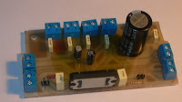
TDA7384 - 4 x 22W car power amplifierIf connect to car battery where operating voltage is about 13.2V, then each channel can give 22W(4Ω) – what is more than enough for me. This amplifier I probably will use to test audio processor TDA7313 which is stil in development phase.

I didn’t find much information about this chip on the internet so I decided to built it and try on my own. As datasheets of TDA7384 says it is low distortion, low output noise, low external component count. Also has Stand-By function and Mute function. It has several protections like from output short circuit to GND or to Vs, capable to handle very inductive loads, thermal limiter, load dump voltage. TDA7384 is an AB power amplifier cased in flexiwatt25 (eagle library is included in project archive) package wich is designed for high end car radio applications. It allows rail to rail output voltage swing with no need of boot-strap capacitors.

Schematics TDA7384
Schematics TDA7384


I have followed the schematic in datasheed when building circuit. In datasheet you may also find PCB layout but it is two layered and didn’t fit to may box I’ve chosen. So I have made single sided PCB 50X100mm.


PCB TDA7384 amplifier

As I put pins on PCB for ST-BY and Mute but I not using them, I connected these pins to VCC like it is shown in PCB view. According to datasheet St-By and Mute turns off amplifier if signal in input is lower than 3.5V. So it is recommended to connect these pins to Vcc if not used.
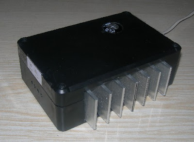
Maximum power dissipation of chip is 80W(Tcase=70ºC), so it can handle 4 channels working at power of 20W each. But of course chip in a box doesn’t have good ventilation so I’ve put a radiator to ensure that amplifier effectively dissipates heats. I didn’t try to load amplifier to maximum to se if it doesn’t heat up to much. But at normal sound level it stays warm what is normal.


On box amplifier
On box amplifier


Dont forget to put thermal paste between chip and radiator to ensure lower thermal resistance. And here we go – brand new power amplifier ready to go:


TDA7384 Already to use
Already to use


source: [link]
Read More..

Saturday, November 30, 2013

Subowoofer audio car amplifier

For the a one amplifier circuit is very suitable for use in applications subwoofer speaker, which allows for higher spending enough bass. Although output was spent not high, but for bass sounds do not undoubtedly. Indeed, the output is only 20W mono amplifier with 8 ohm impedance. With a maximum supply 44Volt DC.
car subwoofer
Part list
R1 = 47R
R2 = 100K
R3 = 1R 2W
C1 = 2.2uF
C2 = 220uF
C3 = 100uF
C4 = 47uF
C5 = 68uF
C6 = 100uF
C7 = 1000uF
C8 = 0.1uF
U1 = STK024 , STK031 ,STK035
Read More..

Friday, November 15, 2013

High power car audio amplifier

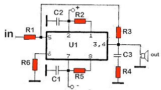
high power car audio amplifierThis is a power amplifier which functioned as the car audio amplifier IC that uses PA02 and LH0101. That each IC has a 30W output power with 8 ohm impedance.


Part List 
R1 = 10K
R2 = 0.15R
R3 = 20K
R4 = 2.7R 1W
R6 = 15R
R7 = 10K
C1 = 0.1uF
C2 = 0.1uF
C3 = 0.1uF
IC = LH0101 , PA02
high power car amplifier circuit


Supply voltage from 7 volts to 25 volts. For a car battery can also be used but must be first converted into voltage +, -, and ground. Following a series of amplifier.

Read More..

Wednesday, November 13, 2013

50W car audio amplifier schematic circuits

50W car amplifier schematicsCar power amplifier uses SI1050GL IC as the main amplifier. The output power 50 Watt 8 ohm mono impedance. Up to 25 Volt DC voltage. with source voltage of this amplifier car battery has to work.

Minimum of 12 Volt battery voltage, less than a sound or audio is issued less than the maximum and less good. You can assemble  this circuit amplifier with a schema like this.
50W car amplifier system
Part List
R1 = 100K
R2 = 1R
C1 = 2.2uF
C2 = 22uF
C3 = 100uF
C4 = 0.1uF
C5 = 100uF
U1 = SI1050GL
If you want to make stereo amplifier , you must required multiply the two of components. 


Read More..

A Pioneer In Their Own Right The Pioneer Car Stereo

Look at any good car stereo system and you’ll probably see a Pioneer car stereo unit plugged into the console. Alongside with quality speakers and a strong lineup of accessories like LCD panels and navigational devices, Pioneer products/Pioneer car stereos have earned a huge following the world over.  

The Pioneer Company is a Tokyo-based corporation, and is one of the world leaders in digital entertainment products. The Pioneer Company was first founded in 1938 in Tokyo as a small radio and speaker repair shop business but today, they are recognized as a leader in technology advancements in the consumer electronics industry.
A Pioneer In Their Own Right: The Pioneer Car Stereo
The company is truly deserving of their name. They are respected for many innovations such as interactive cable TV, the Laser Disc player, developing the first Compact Disc player for the car and the first detachable face car stereo, DVD and DVD recording, plasma display, and organic electroluminescent display. Their strength in optical disc and display technology is complemented by its state-of-the-art software products and manufacturing capabilities.

Nowadays, Pioneer car stereo units are not just simple head units. A car stereo can easily be comprised of several items built into the console of the car. Hardware like navigational devices, DVD players with LCD panels, coupled with the standard array of compact disc, mp3 and cassette players now usually go together. One would be hard-pressed not to acquire all of these, as it is such a delight to see these units work harmoniously. But traditionally, a Pioneer car stereo unit is a head unit with a radio, cassette and cd player. No matter how bare-bones this might sound, anyone will surely be impressed with the sound quality and features a Pioneer car stereo can boot.

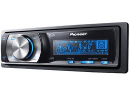
Something like the DEH-P90HDD Pioneer car stereo single CD player head unit. The DEH-P90HDD allows you to record CD Audio (from the unit itself or from a changer) onto a 10GB hard disc drive, which holds about 200 audio CDs (using ATRAC3 digital compression). Your CDs are recognized by the pre-installed Gracenote CDDB database, which includes auto-playlists that make finding a specific CD easy. This Pioneer car stereo unit can also play your MP3 CDs plus CD Audio, CD-RW, and CD-R discs. Also, the MagicGate Memory Stick player lets you play recorded Memory Stick tracks. The Organic EL display is easy to read and accepts image downloads, so you can customize its look. Built-in DSP offers a 13-band graphic EQ and a huge variety of tools. The DEH-P90HDD is XM Ready and provides a steering wheel remote.   

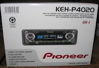
KEH-P4020 Pioneer
If cassettes are your thing, the KEH-P4020 Pioneer car stereo cassette player head unit is a good product to choose. It is a full logic cassette system with multi-color display, 45Wx4 High Power, EEQ™ equalizer system, Tuner, IP-Bus System Control, flap face and has a detachable face security. 

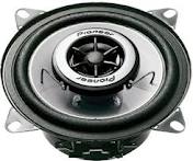
Pioneer speakersIf you’re planning to buy a Pioneer car stereo unit, why not match it with a set of Pioneer speakers too? Pioneer car stereo has made another innovation in their REV Series speakers, which incorporates technological breakthroughs in their IASCA award-winning Premier Reference Series (PRS) speakers. Rev Series speakers boast Pioneer’s Kevlar Fiber Composite Cones, Soft-dome tweeters and Wave guides. Each speaker features a bright yellow cone and distinctive wave guides, plus a six-spoke grill with a titanium finish that simulates chrome wheels.


With all these impressive products, is it still a wonder why they call Pioneer car stereos “Pioneer”?

Read More..

Sunday, November 10, 2013

Car audio amplifier with IC TA7203P

Stereo car power amplfier with TA7203P , is suitable for the room your car , your car it will build an increasingly crowded and felt like using high-class amplifiers and speakers. Simply using this circuit and some speaker subwoofer speakers you can enjoy it.
Technical information :
Max voltage = 20 Volt
Min voltage = 8 Volt
Max output  = 2 x 40 Watt
RL               = 8 Ohm
Read More..