

Consumer appliances these days hardly ever have a proper mains switch. Instead, appliances are turned on and off at the touch of a button on the remote control, just like any other function. This circuit shows how a device (as long as it does not draw too high a current) can be switched on and off using a pushbutton. The approach requires that a microcontroller is already available in the circuit, and a spare input port pin and a spare output port pin are required, along with a little software. When power is applied T1 initially remains turned off. When the button is pressed the gate of T1 is taken to ground and the p-channel power MOSFET conducts. The microcontroller circuit is now supplied with power. Within a short period the microcontroller must take output PB1 high. This turns on n-channel MOSFET T1 which in turn keeps T1 turned on after the push-button is released.
Now the microcontroller must poll the state of the push-button on its input port (PB0) at regular intervals. Immediately after switch-on it will detect that the button is pressed (a low level on the input port pin), and it must wait for the button to be released. When the button is next pressed the device must switch itself of f: to do this the firmware running in the microcontroller must set the output port pin to a low level. When the button is subsequently released T1 will now turn off and the supply voltage will be removed from the circuit.
The circuit itself draws no current in the off state, and for (rechargeable) battery-powered appliances it is therefore best to put the switch before the voltage regulator. For mains-powered devices the switch can also be fitted before the voltage regulator (after the rectifier and smoothing capacitor). Since there is no mains switch there will still be a small standby current draw in this case due to the transformer. Be careful not to exceed the maximum gate-source voltage specification for T1: the IRFD9024 device suggested can withstand up to 20 V. At lower voltages R2 can be replaced by a wire link; otherwise suitable values for the voltage divider formed by R1 and R2 must be selected.
Circuit diagram: The Gentle Touch Circuit Diagram
The author has set up a small website for this project at http://reweb.fh-weingarten.de/elektor, which gives source code examples (which include dealing with pushbutton contact bounce) for AVR microcontrollers suitable for use with AVR Studio and GNU C. Downloads are also available at http://www.elektor.com.



 For those long and sometimes lonely miles your auto sound system is the voice of reason, the energetic beat, and the information that keeps you up on current events, weather forecasts, and what is going on in the world of the rich and famous. Even if you arent all that into music there is the wide and wonderful world of talk radio that keeps many of us informed and inflamed about issues that are important to us and causes which we feel passionately about.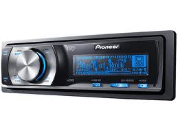
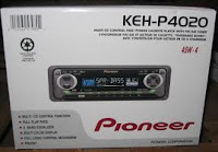
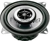 If you’re planning to buy a Pioneer car stereo unit, why not match it with a set of Pioneer speakers too? Pioneer car stereo has made another innovation in their REV Series speakers, which incorporates technological breakthroughs in their IASCA award-winning Premier Reference Series (PRS) speakers. Rev Series speakers boast Pioneer’s Kevlar Fiber Composite Cones, Soft-dome tweeters and Wave guides. Each speaker features a bright yellow cone and distinctive wave guides, plus a six-spoke grill with a titanium finish that simulates chrome wheels.