Showing posts with label light. Show all posts
Showing posts with label light. Show all posts
Thursday, October 23, 2014
Simple Emergency Light
This is an automatic emergency lamp with day light sensing, means it senses darkness/night and turns ON automatically. Similarly it senses day light and turns OFF automatically. A simple emergency lamp which does not require any special equipment; even a multimeter to assemble and use. Any individual who can do a good quality soldering must be able to build this circuit successfully.
This can be easily accommodated in the defunct two 6 watt tube National Emergency Lamp or any PL tube type emergency lamp. The difference will be in the working; it will work non stop for more than 8 hours.deep discharge is taken care by the LED characteristic and over charge protection is taken care by the fixed voltage regulator.This uses a simple 3Pin fixed regulator which has a built in current limiting circuit.
Simple Emergency Light Circuit Diagram:

This can be easily accommodated in the defunct two 6 watt tube National Emergency Lamp or any PL tube type emergency lamp. The difference will be in the working; it will work non stop for more than 8 hours.deep discharge is taken care by the LED characteristic and over charge protection is taken care by the fixed voltage regulator.This uses a simple 3Pin fixed regulator which has a built in current limiting circuit.
Simple Emergency Light Circuit Diagram:
The only required adjustment is the preset which has to be set to ensure the LEDs just light up (it should be left at that position). The 5mm LDR is just mounted on top of the emergency light as shown in the photograph. LDR is used to avoid it lighting up during day time or when the room lights are ON. 2 LEDs are used in series; the dropping resistance is avoided and 2 LEDs light up with current that is required for a single LED, by which energy is saved to a great extent.
This particular circuit has been kept so simple for people who has limited access to components or in other words this is an emergency light that you can build with minimum components. In addition to circuit diagram, He has shared photographs of the prototype he made in National emergency light and a PCB design.
This particular circuit has been kept so simple for people who has limited access to components or in other words this is an emergency light that you can build with minimum components. In addition to circuit diagram, He has shared photographs of the prototype he made in National emergency light and a PCB design.
http://www.extremecircuits.net

Monday, October 20, 2014
How Put that Light Out! Circuit Diagram
If you forget to switch off the light after leaving a seldom used room (such as the loft), there’s a strong likelihood that it could remain lit for months, running up an expensive power bill in the process. How can we prevent this waste?
It’s not hard for electronics enthusiasts to design a little circuit to mitigate the effects of absentmindedness. The notion is simple; if the light is left on when the hatch or door is closed, a rhythmic sounder/buzzer signal produces an alarm that hopefully will not be masked by other noise.
Circuit Diagram:
It’s not hard for electronics enthusiasts to design a little circuit to mitigate the effects of absentmindedness. The notion is simple; if the light is left on when the hatch or door is closed, a rhythmic sounder/buzzer signal produces an alarm that hopefully will not be masked by other noise.
Circuit Diagram:

The circuit is powered as long as the lamp bulb is switched on by light switch S1. If the reed switch S2 then signals that the hatch has been closed, the sounder operates. The red LED, mounted outside the loft next to the entry hatch, also indicates that the lamp up there needs to be switched off. The circuit does not use a transformer, meaning that the whole circuit is at mains potential. For this reason the components must be placed inside an insulated plastic case for protection, with no way that people can touch any part of the circuit (this includes the sounder).
The connecting wires to the LED and the reed switch contact must be fully protected to the same touch-proof degree too. For the sounder you can use any type that operates on direct current in the region between 1 V and 3 V. In this circuit the operating voltage is limited by the LED connected in parallel to the buzzer. Using a red LED will provide around 1.7 V to the sounder. The current requirement of this kind of miniature sounder is about 5 mA.
Author: Stefan Hoffmann - Copyright: Elektor
Monday, December 9, 2013
Designing a Light Detection
In designing a circuit that can detect light, the most important component is the light sensor. One of the light sensor that we often encounter is LDR (Light Dependent Resistor).
Introducing the Light Sensor
LDR resistance changes with changes in light intensity hit it. In the dark, the LDR resistant is about 10 Mohm and the sunniness of 1 kohm or less. LDR is made from semiconductor materials such as cadmium sulfide. With this material, the light energy that falls cause more load is released or the electric current increased payload. That is, the resistance of the material decreases.
LDR is used to convert light energy into electrical energy. Automatic switches and burglar alarms are a few examples of tools that use the LDR. Because the response to light enough slow, LDR is not used in situations where the light intensity changed drastically.
Characteristics of LDR:
1. At the time not given light, LDR has a very high resistance could reach 10 Mohms
2. But when given a light, the barriers will come down drastically so that the voltage and current can pass through the LDR.
So how do we use the characteristics of the LDR to construct a light detector circuit?
Surely this LDR will be combined with other components. Here is an example circuit with LDR and other components.
Introducing the Light Sensor
LDR resistance changes with changes in light intensity hit it. In the dark, the LDR resistant is about 10 Mohm and the sunniness of 1 kohm or less. LDR is made from semiconductor materials such as cadmium sulfide. With this material, the light energy that falls cause more load is released or the electric current increased payload. That is, the resistance of the material decreases.
LDR is used to convert light energy into electrical energy. Automatic switches and burglar alarms are a few examples of tools that use the LDR. Because the response to light enough slow, LDR is not used in situations where the light intensity changed drastically.
Characteristics of LDR:
1. At the time not given light, LDR has a very high resistance could reach 10 Mohms
2. But when given a light, the barriers will come down drastically so that the voltage and current can pass through the LDR.
So how do we use the characteristics of the LDR to construct a light detector circuit?
Surely this LDR will be combined with other components. Here is an example circuit with LDR and other components.

From the picture above, we can set (varying) the value of R1, R2 and potentiometer P1.
V+ = (RLDR / R1 + RLDR ) 5V
V- = (P1 / R2 + P1) 5V
For example we want to turn on lights automatically when dusk and the lights off automatically when the early morning. Here we can set the reference voltage to be compared with the input voltage of the LDR, we can set these voltages to match the surrounding light intensity.
V+ = (RLDR / R1 + RLDR ) 5V
V- = (P1 / R2 + P1) 5V
For example we want to turn on lights automatically when dusk and the lights off automatically when the early morning. Here we can set the reference voltage to be compared with the input voltage of the LDR, we can set these voltages to match the surrounding light intensity.
Monday, December 2, 2013
Light sensor component
Electronic components are included in the category of light sensors are as follows:
Read More..
- LDR
- Photo Transistor
- Photo Diode
- Infrared Receiver
The function of the electronic component is to detect the intensity of light received by the component. The light sensor is often used in electronic equipment such as on television, light a light switch, light intensity measuring instrument.
Thursday, November 21, 2013
Traffic Light 20 Chanel based on 74LSxx
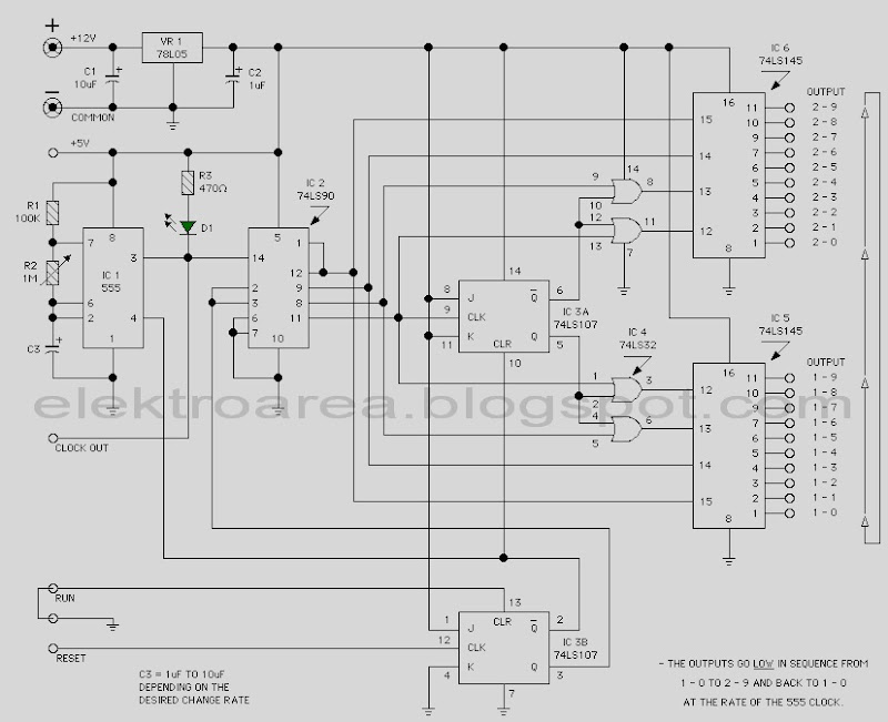 Traffic Light 20 Chanel based on 74LSxx
This view of the proposed traffic Light 20 Chane based only on family and 74LSxx IC 555 as clock source. It is a digital logic circuit. To construct the traffic light rangkaian Control requires no programming of microcontrollers.
This page features a circuit that has twenty open collector outputs that turn on one at a time in a continuous sequence. The circuit make use of the family 74LSxx TTL integrated logic devices. The circuits are designed to drive light emitting diodes or low current and low voltage incandescent lamps, but can also lead to other charges of 80 milliamps.
notes:
This page features a circuit that has twenty open collector outputs that turn on one at a time in a continuous sequence. The circuit make use of the family 74LSxx TTL integrated logic devices. The circuits are designed to drive light emitting diodes or low current and low voltage incandescent lamps, but can also lead to other charges of 80 milliamps.
notes:
- The low output go in sequence from 1 - 0 and back to 1 -0
- At the clock rate of the 555 timer
- c3 = 1uf to 10uf depending on the rate of change desured
- R2 (Variable resistor) in use to determine the timer
Subscribe to:
Posts (Atom)