Showing posts with label on. Show all posts

Thursday, October 23, 2014

Power On Indicator

Some types of electronic equipment do  not provide any indication that they are  actually on when they are switched on.  This situation can occur when the back-light of a display is switched off. In addition, the otherwise mandatory mains  power  indicator  is  not  required  with  equipment  that  consumes  less  than  10 watts. As a result, you can easily forget  to switch off such equipment. If you want  to know whether equipment is still drawing power from the mains, or if you want  to have an indication that the equipment  is switched on without having to modify the equipment, this circuit provides a solution. 

image

One way to detect AC power current and  generate a reasonably constant voltage  independent of the load is to connect a  string of diodes wired in reverse parallel in series with one of the AC supply  leads. Here we selected diodes rated  at 6 A that can handle a non-repetitive  peak current of 200 A. The peak current  rating is important in connection with  switch-on  currents.  An  advantage  of  the selected diodes is that their voltage  drop increases at high currents (to 1.2 V  at 6 A). This means that you can roughly  estimate the power consumption from  the brightness of the LED (at very low  power levels). The voltage across the diodes serves as  the supply voltage for the LED driver. To  increase the sensitivity of the circuit, a  cascade circuit (voltage doubler) consisting of C1, D7, D8 and C2 is used to double  the voltage from D1–D6. Another benefit  of this arrangement is that both halve- waves of the AC current are used. We use  Schottky diodes in the cascade circuit to  minimise the voltage losses. 

Power On Indicator-Circuit-Diagram
Power On Indicator Circuit Diagram

The LED driver is designed to operate the LED  in blinking mode. This increases the amount  of current that can flow though the LED when  it is on, so the brightness is adequate even  with small loads. We chose a duty cycle of pproximately 5 seconds off and 0.5 second  on. If we assume a current of 2 mA for good  brightness with a low-current LED and we can  tolerate a 1-V drop in the supply voltage, the  smoothing capacitor (C2) must have a value of  1000 µF. We use an astable multivibrator built around two transistors to implement a  high-efficiency LED flasher. It is dimensioned to minimise the drive current of  the transistors. The average current consumption is approximately 0.5 mA with a  supply voltage of 3 V (2.7 mA when the  LED is on; 0.2 mA when it is off). C4 and  R4 determine the on time of the LED (0.5  to 0.6 s, depending on the supply volt-age). The LED off time is determined by  C3 and R3 and is slightly less than 5 seconds. The theoretical value is R × C × ln2,  but the actual value differs slightly due to  the low supply voltage and the selected  component values.
 
Diodes D1-D6 do not have to be special  high-voltage diodes; the reverse volt-age is only a couple of volts here due  the reverse-parallel arrangement. This  voltage drop is negligible compared to  the value of the mains voltage. The only  thing you have to pay attention to is the  maximum load. Diodes with a higher  current rating must be used above 1 kW.  In addition, the diodes may require cool-ing at such high power levels.  Measurements on D1–D6 indicate that  the voltage drop across each diode is  approximately 0.4 V at a current of 1 mA.  Our aim was to have the circuit give a  reasonable indication at current levels  of 1 mA and higher, and we succeeded  nicely. However, it is essential to use a  good low-current LED.
 
Caution: the entire circuit is at AC power potential. Never work on the circuit with the mains cable plugged in. The  best enclosure for the circuit is a small,  translucent box with the same colour as  the LED. Use reliable strain reliefs for the  mains cables entering and leaving the  box (connected to a junction box, for  example). The LED insulation does not  meet the requirements of any defined insulation class, so it must be fitted such that it  cannot be touched, which means it cannot  protrude from the enclosure.
Read More..

Friday, September 26, 2014

How to connect LCD Display on the Arduino using only 2 pins

Generally for connecting an LCD display to an Arduino using 7 strands, it usually breaks the leg that has any projects that remain few ports to be used. But there is a way, using an IC 74LS164 (8-bit serial shift register), a resistor and a diode, but its not just hardware, you have to use a library.

This Arduino library for connection of 2-wire or 3-wire using HD44780 compatible LCD display via shiftregisters. This circuit is considered "deprecated", but its worth testing.

LCD Display on the Arduino Circuit 

LCD Display on the Arduino

Read More..

Tuesday, January 28, 2014

Process formation of RGB signal on TV

Basically the UOC is equipped with RGB or YUV input from external, so it is possible to use the DVD input. Selection of these inputs can be done internally within the IC.  But in the G7 and G7A chassis input YUV signal is not used, so in the ground.


RGB signal processing flow is described according to the image below :

iagram of the formation RGB signal
Diagram of the formation RGB signal


1. Signal Yint, uint, and Vint is derived from a series of color decoder and Y / C switch is fed into a series of YUV selector 1.

2. From YUV selector, sub-carrier signal color (U and V) is inserted into the chain matrix. In this matrix series component sub-carrier signal BY of the color (U signal) and BY component of sub-carrier signal color (V signal) in separate. Here the color difference signal in the form of the color sub carrier. GY signal generated by a combination of color difference signals RY and BY.

3. From YUV selector, luminan signal is passed to a series of black stretch. The working principle is to sharpen the series of black stretch black levels. Gray color in a certain percentage in drag to a black color so the color is sharper.

4. Three color difference signals (RY), (BY) (GY) and luminan signal (Y) are mixed and processed in RGB adder circuit to produce three primary colors red, green and blue (RGB).

5. RGBOSD formed in the UOC IC is used to display the OSD text. The selection and arrangement RGBOSD kontrast between RGB and composite signals is done by way of a switch by the internal microprocessor.

6. Three output video signal (RGB signal) is assumed as the current that flows to the CRT cathode. Drive level coming into the cathode tube is always diadjust by CCC loop (Continues Cathode Calibration) and feedback currents in pass to Black Current Input pin 50.

7. CCC loop works as a stabilizer against the black level and drive the cathode in a loop (continuous) to the RGB signal in order to obtain the proper offset and gain.

CCC Loop Application


Read More..

Thursday, December 12, 2013

Solving the problem on tv tuner

Solve problem on tv tuner
Tv tuner serves as the catcher signals from the antenna. Damage tuner, among others:
1. Image does not exist and there is no sound, raster speckled thick.
2. No picture no sound, or otherwise.
3. Channel switching the channel itself.
4. Image blocking white or blue.


How to check the tuner and the IF is to remove the tuner from the PCB and connected by cable to the IF path, BM and Ground, then prepared using the pin on the tuner. Then the television was turned on, the antenna is connected to the antenna socket, and RV or potensio rotated slowly to choose the television channel when the tuner is in normal condition, the signal from the antenna to be acceptable, the picture and sound, and the channels do not move themselves. To damage its own channel switch and checked the normal manner stated above, the location of damage on the section of the program.
Read More..

Saturday, November 23, 2013

AT89S51 Microcontroller based on Digital Clock

AT89S51 Microcontroller based on Digital Clock
Digital hours to create this not too tough. This series is not my original project, I trace the series of files and program from the internet, there is no chance the program listing. when I download the file to its hex-hour direct approach. This clock only displays hours and minutes, to seconds but youll install the led associated with a series of I Hz oscillator formed from IC 555 (which I do, because I do not recognize the program listing).

a pair of led in parallel and installed as a bookmark seconds. Led to two installed in the middle of the hours and minutes. though with the approach that seconds and minutes if observed (calculated) decline slightly however i am not the problem, Moreover individuals wont understand it.
Read More..

Thursday, November 21, 2013

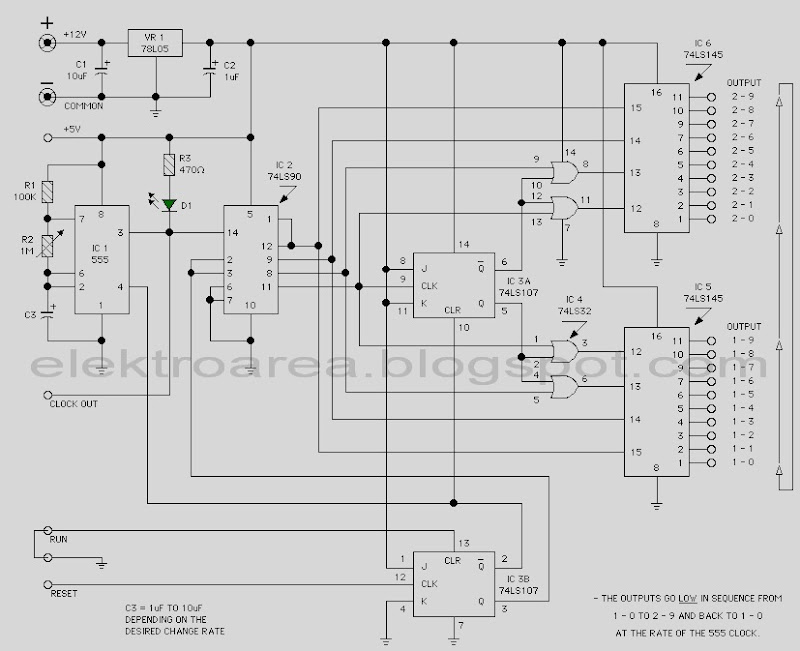
Traffic Light 20 Chanel based on 74LSxx

Traffic Light 20 Chanel based on 74LSxxTraffic Light 20 Chanel based on 74LSxx


This view of the proposed traffic Light 20 Chane based only on family and 74LSxx IC 555 as clock source. It is a digital logic circuit. To construct the traffic light rangkaian Control requires no programming of microcontrollers.


This page features a circuit that has twenty open collector outputs that turn on one at a time in a continuous sequence. The circuit make use of the family 74LSxx TTL integrated logic devices. The circuits are designed to drive light emitting diodes or low current and low voltage incandescent lamps, but can also lead to other charges of 80 milliamps.


notes:

  • The low output go in sequence from 1 - 0 and back to 1 -0

  • At the clock rate of the 555 timer
  • c3 = 1uf to 10uf depending on the rate of change desured
  • R2 (Variable resistor) in use to determine the timer
Read More..