Showing posts with label mini. Show all posts
Showing posts with label mini. Show all posts
Monday, October 20, 2014
Modifying USB OTG Cable Mini USB micro

This is a very simple way to change the standart USB to USB OTG. The Mini or Micro USB to USB does not work if you want to use it for OTG, because 4. pin micro USB plug is not plugged. Connect as shown above.

Mini RS232 Data Switch
Mini RS232 Data Switch. Only simple materials and a little bit of skill are needed to build an RS232 switch. All that you need are two 9-way sub-D plugs with solder pins, a small piece of sheet aluminium, two sets of screw retainer posts, a 4-pole double-throw switch, a strain relief sleeve and a suitable plastic connector shell for a 25-way sub-D connector, with both in-line and right-angle cable entries (such as Conrad Electronics #711322). What is important is that the side cable entry together with its associated strain relief leaves enough room for the switch. If necessary, you may have to cut away a few square millimetres of the sidewall or a few ribs of the plastic shell.
Project image :

Mini RS232 Data Switch Image
The switch is operated via the in-line cable opening, as can be seen from the photo. A suitable switch with an overall length of 29 mm can be found in the Conrad catalogue under order number 708232. The only modification that must be made to the connector shell is to drill two holes for the retaining screws for the switch (M2.6 screws) at a spacing of 24 mm.
Circuit diagram :

Mini RS232 Data Switch Circuit Diagram
Connect the two sub-D connectors together using the piece of aluminium and the screw retainer posts. Then solder the cable to the connectors and the switch as indicated. The two connectors are wired somewhat differently. While the upper sub-D plug is connected 1:1 with the input cable (with the switch in the appropriate position), the DCD, DTR, DSR and RI pins of the lower connector are left open. This is because RTS and CTS are fully sufficient for handshaking, as long as DTR and DSR are connected to each other. The only leads that are switched are RXD, RTS, TSD and CTS. The ground potential is fed from the cable to both connectors. After everything has been properly soldered together, you can fit everything into the cable shell as shown.
Thursday, December 26, 2013
Mini Stereo Power Amplifier using TDA2822
This circuit TDA2822 total to the same extent your primary device. The Dual Amplifier IC before IC stereo increase by 40 dB. Bandwidth 120 kHZ. with the purpose of is regarding 2 watts and watt power supply of 1.8 to 15 volts and a current 6 mA no more than after using the power supply 9 volt into this circuit.VR1 and VR2 to adjust the suggest level of the best and not here, the pin 7 and pin 6 of IC1.The amplifier IC1 is outmoded of the output pin 1 and pin 3, through the C4 and C5 coupling signals to the absent and right speakers.The C6, R1 and C7, R2 is to reduce blast.
 |
| Mini Stereo Power Amplifier using TDA2822 Circuit Diagram |
Sunday, November 24, 2013
Mini and simple power amplifier circuits

What is the meaning of the picture above? The above picture is a miniature audio amplifier and very simple. Here I will give an audio amplifier schematic is very simple which only requires a few components only, can be seen under this scheme.
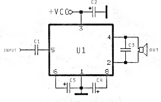
See from above scheme may occur to you, certainly cheap enough to make this amplifier and quite easy to make. The above simple audio amplifier circuit using an IC as the main amplifier and accompanied by other components. IC used is S1513, which requires a supply voltage ranging from 1.5 volts to 6 volts. And only 0.1 W output power with 4 ohm impedance. For a list components can be seen below.
Part list
C1 = 100nF
C2 = 100uF
C2 = 100uF
C3 = 3n3F
C4 = 1uF
C5 = 1uF
U1 = S1513
C5 = 1uF
U1 = S1513
Subscribe to:
Posts (Atom)