Friday, January 31, 2014

Water Tank Level Meter Sensor

The water-tank level meter de-scribed here is very simple and useful for monitoring the water level in an overhead tank (OHT). The water level at 30cm intervals is monitored and continuously indicated by LEDs ar-ranged in a meter-format. When all the LEDs are ‘off’, it indicates that the OHT is empty. When the water level reaches the top limit, the whole LED-meter begins to flash. The height at which the level-sensing electrodes are fitted is adjustable. Thus, the minimum and maximum level settings may be varied as desired. The range of the meter can also be enlarged to cater to any level. No special or critical components are used. CMOS ICs are used to limit the idle current to a minimum level.
 
Even when all the LEDs are ‘on’, i.e. water reaches the top level, the demand on the power supply is reasonably low. Further, the extremely high input resistance of the Schmitt inverter gates reduces the input current and thus minimises the erosion of electrodes. The princi-pal part of the device is its water-level sensor assembly. By using easily available material, it can be fabricated to meet one’s own specific requirements. The common ground reference electrode ‘X’ is an aluminium conduit of 15mm outer diameter and 3-metre length, to cater to a 3-metre deep overhead tank. Insulating spacer rings ‘Y’ (10mm length, 15mm dia.) are fabricated from electrical wiring conduits of 15mm inner diameter.
 
These are pushed tightly over the aluminum conduit at preferred places, say 30cm apart. If the pieces are too tight, they can be heated in boiling water for softening and then pushed over ‘X’. The sensor electrodes ‘Z’ are made out of copper or brass strips (6mm wide and 1mm thick) which are shaped into rings that can tightly slip over the ‘Y’ pieces. The ends of these strips are folded firmly and formed into solder tags S1 to S10 and SG. The wall-mounting brackets, made of aluminium die-cast, are screwed directly on ‘X’ at two suitable places.
 
Water-Tank Level Meter cir 
The sensor cable ‘WC’ wires are soldered to solder tags, and some epoxy cement is applied around the joints and tags to avoid corrosion by water. The common ground reference wire ‘SG’ is taken from tag ‘T’. The cable’s individual wires from S1 to S10 and SG are cut and matched in length for a neat layout. The other ends of the cable are connected to the PCB terminal points S1 to S10 and SG respectively. No separate ground is needed. The electronics portion is simple and straightforward. A long piece of vero board can hold all the parts including the power supply section.
 
For easy installation, the LEDs can be set at the track side of the board, in a single line, so that they may be pushed through the cutouts in the front panel of the enclosure from inside. The water level at 30cm intervals is monitored by corresponding sensors, causing the input  to the concerned inverters (normally pulled  ‘high’ via resistors R1 through R10) to go ‘low’, as soon as water reaches the respective sensors On initial switching  ‘on’ of the power supply, when the tank is empty, all the electrodes are open. As a result, all the inverter inputs are ‘high’ (via the pull-up resistors R1 to R10) and their outputs are all  ‘low’. Thus, all the LEDs are  ‘off ’. As soon as the water starts filling the tank, the rising water level grounds the first sensor.
 
The logic 1 output of first inverter gate N1 causes conduction of transistor T2 to extend ground to one side of resistors R14 through R23 via emitter collector path of transistor T2. The LED D1 is thus lit up. Similarly, other LEDs turn  ‘on’ successively as the water level rises. As soon as the water in OHT reaches the top level, the output of gate N10 goes to logic 1 and causes flashing-type LED D11 to start flashing. At the same time, transistor T1 conducts and cuts off alternately, in synchronism with LED D11’s flash rate, to ground the base of transistor T2 during conduction of transistor T1. As a result, transistor T2 also starts cutting ‘off’ during conduction of transistor T1, to make the LED meter (comprising LEDs D1 through D10) flash and thus warn that the water has reached the top level.
 
When the water level goes down, the reverse happens and each LED is turned ‘off’ successively. The novel feature of this circuit is that whenever the water level is below the first sensor, all the LEDs are ‘off’ and the quiescent current is very low. Thus, a power ‘on’/‘off’ switch is not so essential. Even when the LED-meter is fully on, the cur-rent drawn from the power supply is not more than 120 mA. A heat-sink may, how-ever, be used for transistor T2, if the tank is expected to remain full most of the time. A power supply unit providing unregulated 6V DC to 15V DC at 300mA current is adequate.
 
Caution. A point to be noted is that water  tends to stick to the narrow space at the sensor-spacer junction and can cause a false reading on the LED-meter. This can be avoided if the spacers are made wider than 10 mm.
Author : M.K. Chandra MouleeswAran - Copyright : EFY
Read More..

Thursday, January 30, 2014

170W power amplifier LM4651 and LM4652

170 Watt power amplifier is a power amplifier that is built by IC LM4651 and LM4652.


Part of this power amplifier driver using the LM4651 IC designed specifically for the purpose of the class AB amplifier driver with short circuit protection feature, containing under voltage, thermal shutdown protection and standby functions. Section 170 Watt power amplifier using LM4651 IC with a MOSFET power amplifier is equipped with temperature sensors that will be used by IC LM4651 as controlnya thermal signal. IC IC LM4651 and LM4652 are designed specifically to each other in pairs to create a class AB power amplifier with protection features are detailed. Detailed series of 170 Watt power amplifier can be seen in thethe following figure .

170W power amplifier LM4651 and LM4652

Power amplifier circuit requires supply voltages +22 V DC symmetrical 0-22V. Power Amplifier with IC LM4651 and LM4652 are often used in portable HiFi systems such as powered speakers, power subwoofer and car audio power Booter. D1, D2, D3 and D4 in series 170 watt power amplifier with LM4651 and LM4652 is a 22V zener diode.
Read More..

Tuesday, January 28, 2014

Process formation of RGB signal on TV

Basically the UOC is equipped with RGB or YUV input from external, so it is possible to use the DVD input. Selection of these inputs can be done internally within the IC.  But in the G7 and G7A chassis input YUV signal is not used, so in the ground.


RGB signal processing flow is described according to the image below :

iagram of the formation RGB signal
Diagram of the formation RGB signal


1. Signal Yint, uint, and Vint is derived from a series of color decoder and Y / C switch is fed into a series of YUV selector 1.

2. From YUV selector, sub-carrier signal color (U and V) is inserted into the chain matrix. In this matrix series component sub-carrier signal BY of the color (U signal) and BY component of sub-carrier signal color (V signal) in separate. Here the color difference signal in the form of the color sub carrier. GY signal generated by a combination of color difference signals RY and BY.

3. From YUV selector, luminan signal is passed to a series of black stretch. The working principle is to sharpen the series of black stretch black levels. Gray color in a certain percentage in drag to a black color so the color is sharper.

4. Three color difference signals (RY), (BY) (GY) and luminan signal (Y) are mixed and processed in RGB adder circuit to produce three primary colors red, green and blue (RGB).

5. RGBOSD formed in the UOC IC is used to display the OSD text. The selection and arrangement RGBOSD kontrast between RGB and composite signals is done by way of a switch by the internal microprocessor.

6. Three output video signal (RGB signal) is assumed as the current that flows to the CRT cathode. Drive level coming into the cathode tube is always diadjust by CCC loop (Continues Cathode Calibration) and feedback currents in pass to Black Current Input pin 50.

7. CCC loop works as a stabilizer against the black level and drive the cathode in a loop (continuous) to the RGB signal in order to obtain the proper offset and gain.

CCC Loop Application


Read More..

Monday, January 27, 2014

Simple Amplifier with C945 MJE340 and TIP3055

This simple amplifier does sound good quality Power output about 10 - 14 Watts with Supply voltage about 34 - 36 Volt DC. It requires a preamp in the function of it hasnt got much advance. It requires cumbersome heat up sinks and a great transformer and a enormous power supply and alert wiring, but taking part in the bottom it is enormously regular and it sounds very good. The zener diode rubbish every wave future from the power supply, But you still barely aspire a ripple of 10mV be very successful. The swell triumph the input is enlarged, so the zener diode gets free of with the intention of, but whatever swell in attendance is wish still catch the power stage. The Buffer Stage using transistor C945 , Driver Stage Using MJE340 and Booster Stage using TIP3055 . The Transistor are using NPN transitor.

Simple Amplifier using with MJE340 TIP3055 Circuit
Simple Amplifier using with MJE340 TIP3055 Schematic Circuit Diagram
Read More..

Sunday, January 26, 2014

12 Volt Charger Circuit with LM350

The strength supply routine structure is developed as a resource of continuous present with adverse heat range coefficient. Transistor Q1 (BD 140) is used as a heat range indicator. transistor Q2 is used to avoid the strength supply from discharging through R1 when strength is out of stock. Getting routine is developed depending on the LM350 present regulator IC. The result present of the battery charger can be altered between 13-15 V by various the POT R6.


LM350 will try to keep the present decrease between the feedback pin and result pin at a continuous value of 1.25V. So there will be a continuous present circulation through resistor R1. Q1 act here as a heat range indicator with the help of R6/R3/R4 elements that are more or less manages the platform present of Q1. As relationship emitter / platform of transistor Q1, the same as other semiconductors, containing the heat range coefficient of-2mV / ° C, the present result will also display a bad heat range coefficient. This one is just a aspect of 4 huge, because the difference of the emitter / platform of Q1 is increased by a aspect of category P1/R3/R4. This causes some-8mV / ° C. LED will lighting whenever strength is available.
Read More..

Saturday, January 25, 2014

Box Kit Home Theaters

Box Kit Home Theaters | We live in a world where convenience is increasingly growing in demand. For this reason many home theater buyers expect convenience when it comes to the purchase and set up of their home theater systems. It goes without saying that there are all kinds of consumers in the world and even in matters of convenience supply and demand have not emerged to create a one size fits all society. We all want similar things in many ways yet we still want autonomy and selections from which to choose.


Box Kit Home Theaters

The demands of a society that likes the ease of buying prepackaged goods have reached such a point however that packages are common place in everything from prepackaged dinners to prepackaged home theater systems. On one level these types of prepackaged theater systems provide a great deal of convenience to consumers. Among those benefits is the ability to know the cost of the entire system up front. This is actually a small benefit when compared to some of the other benefits that consumers who purchase these systems experience.

Read More..

Friday, January 24, 2014

Zero Crossing Detector Circuit

Zero Crossing Detector circuit is basically an application of a comparator. In the article series Zero Crossing Detector with Op Amp is built using a comparator of an Op Amp IC741/351. The process of detection of this comparator is  0Volt input signal crossing point by making reference value at comparator 0Volt.


 The output of the Zero Crossing Detector circuit with Op Amp is wave-shaped box that detection result of the crossroads of 0 volt input signal.
Read More..

Thursday, January 23, 2014

6 to 12 Volt Power Supply Inverter

This inverter circuit can provide up to 800mA of 12V power from a 6V supply. For example, you could run 12V car accessories in a 6V (British?) car. The circuit is simple, about 75% efficient and quite useful. By changing just a few components, you can also modify it for different voltages.


6 to 12 Volt Power Supply Inverter


Part List:

R1, R4 2.2K 1/4W Resistor

R2, R3 4.7K 1/4W Resistor

R5 1K 1/4W Resistor

R6 1.5K 1/4W Resistor

R7 33K 1/4W Resistor

R8 10K 1/4W Resistor

C1,C2 0.1uF Ceramic Disc Capacitor

C3 470uF 25V Electrolytic Capcitor

D1 1N914 Diode

D2 1N4004 Diode

D3 12V 400mW Zener Diode

Q1, Q2, Q4 BC547 NPN Transistor

Q3 BD679 NPN Transistor

L1 See Notes

MISC Heatsink For Q3, Binding Posts (For Input/Output), Wire, Board

source:LINK
Read More..

Wednesday, January 22, 2014

Wireless Mains Voltage Tester

This circuit can be used to test whether mains voltage is present or not without having electric contact with mains line. The CMOS IC CD4033 is the heart of this circuit. The CD4033 consists of a 5 stage decade Johnson counter and an output decoder for converting the Johnson code to a 7 segment decoded output for driving 7 segment LED display. A 10cm long insulated copper wire connected to the clock pin (pin1) of the IC serves as the sensor.

Wireless Mains Voltage Tester Circuit diagram:


The sensor wire has to be placed in the vicinity of the mains wire to be tested. When there is no voltage in the mains line, no voltage will be induced in the sensor wire and the display will show a random digit. When there is voltage in the mains line, a small voltage will be induced in the sensor wire due to electromagnetic induction and this voltage is sufficient enough to clock the CMOS IC CD4033. Now the display will count from zero to nine and repeat.

Notes:

  • The circuit can be assembled on a Vero board.
  • Use 9V PP3 battery for powering the circuit.
  • Use a 10cm insulated wire as the sensor.
  • The IC must be mounted on a holder.
  • Switch S1 can be a miniature ON/OFF switch.
Read More..

Tuesday, January 21, 2014

OCL Power Amplifier Circuit MJ15003 MJ15004


This Power Amp OCL 100 watt circuit by transistors.They has been an old circuits, but very well amplifier schematic.
We use only all transistor MJ15003 and MJ15004 is the main in circuits, and the power supply +38V 0 -38V 3A. follow stye of OCL amp and They has Spec are
power output : 105watt at 4 ohm load, 88watt at 8 ohms load
input sensitivity : 0.5V
Frequency response : 10-10kHZ +/- 1dB
THD: 0.07% at 50 watt , 0.1% at 100 watt.

This power amp OCL 100w is a very excellent sound quality. Since we provide the circuit in look All direct coupling form is connection join together direct all, to cut-off frequency low-loss problems, the super bass really do not tell who.
The signal Input of the tone controls enter via C1 to the base pin of transistor Q1, which together with the Q2 is differential amplifier, the signal from the collection pin of Q1 supplied to the bas pin of the Q5, which it acts as the pre-driver circuit.
- The transistor Q4 is setting level bias or act as to control Idle current in this circuit. Which we can adjust level idle current by By adjusting the VR1.
- The transistor Q3 acts as a boost trapping.
- The output signal from the Q5 will enter to base pin of Q8,Q9.which acts as the driver circuit. For the signal output to drive the output transistors Q10, Q11.
- Both output transistors Q10, Q11, we used the number on the circuit are MJ15003, MJ15004. This couple can use up to 200W, so not problem in durability.
If you want to save. May be represented by a pair of output are 2N3055, MJ2955 each of the two parallel each other instead.

OCL Power Amplifier Circuit MJ15003,MJ15004
100W OCL Power Amplifier Circuit MJ15003,MJ15004

Creation
-Check the assembly of all equipment to correct the circuit, without the output transistors, Using a voltmeter measure the voltage at the speaker. By also does not have a speaker. At the end of this process was completed and ready to operate immediately.
-Put the power supply to the circuit, then to measure the voltage is 0V or not higher than 0.25V, if not in this means that the circuit failure, need to check first.
-The later, on output transistors, and then use an ammeter to measure the current is supplied with short input circuit. Measuring that positive or negative wire. Then, adjust VR1 until reading about the current 20-40 mA.
- For transistor Q4, when the device successfully. Should be installed on the cooling pad. Which installation of the output transistor. To help control the the bias current output relative to the temperature change of the output transistor.
- The power supply circuit is got by power of transformer T1, which provides voltage to the coil in the secondary coil is 27-0-27 volt, 5 amp.
- The Diodes Bridge rectifier should be not lower than 5 Amp 100V, The filter capacitor C7, C8 we used a 1,000uF 50V, the voltage at the capacitor afer through the filter will can about 38V.
Read More..

Monday, January 20, 2014

700W Power Amplifier with 2SC5200 2SA1943

700W Amplifier Adjust the amplifier power 700W looks calm, but we requirement not put out of your mind to the adjustment happening forcing transistors, the whole relating to-engagement of frequency offset. It is compulsory to change the current insurance rule which serves to guard the final transistors. Their tendency to happen allowable to keep the transistors in the SOAR characteristics. primary it was needed to evaluate all the necessary resistors and subsequently measured to verify the accuracy of the calculations, it is managed with satisfactory results. Peripheral changes required in support of it to be there able to consistently amplifier to supply power. - First you need to restore the 2k2 resistors stylish string with the LEDs on Zenerovými resistors with upper wattage. be enough 1/2W resistors, power loss next to 80V +-based 1W. - therefore was traded 1k2 resistor in the pointer resistor by the side of 620 ohms. 

700W Power Amplifier with 2SC5200, 2SA1943
700W Power Amplifier with 2SC5200, 2SA1943 Circuit Diagram
Which is the initial reap has doubled, so at this point is the overall gain amplifier 40 and the limit excitation is sufficient to 1V rms. - Předbudiči transistors were replaced by stronger MJE15032/33 since KF467/470 are permitted satellite dish current 20mA - by the side of the exciter output stages are used the same transistors for example the output stage. - add up to of terminals of transistors has been increased to eight pairs - It had to occur to compensate designed for the excitation level by calculation a capacitor 10pF to 47pF + 22K appendage. This led to a slight "gradual" amplifiers, but this did not affect the ensuing parameters. This power is tuned correctly in support of this type of terminal transistors 2SA1943/2SC5200. 

With with the purpose of it is a least assessment next to which the amplifier operates stably exclusive of pass by the side of the rising and falling edges of the genuine. - The ultimate adjustment, the adjustment terminal current protection transistor. The SOAR transistor characteristics shows with the intention of the most allowable radio dish current once the voltage of 1.5 A is ideal in favor of cooling, so its essentially not as much of. Therefore, the current protection is customary to 12A, single-arm. This impersonate protection SOAR transistor characteristics. curt-circuit current is regarding 6 A which is about 075A for every transistor. This is far beneath the SOAR characteristics. The mechanical design is relatively clear-cut, the transistors are placed on the two cooling profiles with a height of 66 mm, width 44mm, overall part 260mm. They are twisted contrary to each one other in this way, from the cooling tunnel. Coolers are attaching the nylon aid which allows the compilation of transistors exclusive of washers, and thus better conveying tepla.DPS amplifier next to the top of the tunnel and the transistors are soldered from the underside of PCB.

Read More..

Sunday, January 19, 2014

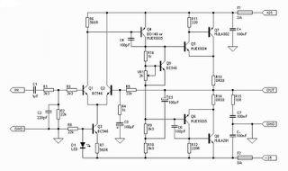
Hi Fi 25W Power Amplifier Class A

Hi-Fi 25W Power Amplifier (Class-A) Schematics Circuit
Hi-Fi 25W Power Amplifier (Class-A)
Click to view larger
Read More..

Saturday, January 18, 2014

Mobile Bug Detector

This
handy, pocket-size mobile transmission detector can sense the presence
of an activated mobile phone from a distance of one-and-a-half metres.
So it can be used to prevent use of mobile phones in examination
halls, confidential rooms, etc. It is also useful for detecting the use
of mobile phone for spying and unauthorised video transmission. The
circuit can detect both the incoming and outgoing calls, SMS and video
transmission even if the mobile phone is kept in the silent mode.

The
moment the bug detects RF transmission signal from an activated mobile
phone, it starts sounding a beep alarm and the LED blinks. The alarm
continues until the signal transmission ceases. An ordinary RF detector
using tuned LC circuits is not suitable for detecting signals in the
GHz frequency band used in mobile phones. The transmission frequency of
mobile phones ranges from 0.9 to 3 GHz with a wavelength of 3.3 to 10
cm. So a circuit detecting gigahertz signals is required for a mobile
bug.

Here the circuit uses a 0.22µF disk capacitor (C3) to
capture the RF signals from the mobile phone. The lead length of the
capacitor is fixed as 18 mm with a spacing of 8 mm between the leads to
get the desired frequency. The disk capacitor along with the leads acts
as a small gigahertz loop antenna to collect the RF signals from the
mobile phone. Op-amp IC CA3130 (IC1) is used in the circuit as a
current-to-voltage converter with capacitor C3 connected between its
inverting and non-inverting inputs.

It is a CMOS version using
gate-protected p-channel MOSFET transistors in the input to provide very
high input impedance, very low input current and very high speed of
performance. The output CMOS transistor is capable of swinging the
output voltage to within 10 mV of either supply voltage terminal.
Capacitor C3 in conjunction with the lead inductance acts as a
transmission line that intercepts the signals from the mobile phone.
This capacitor creates a field, stores energy and transfers the stored
energy in the form of minute current to the inputs of IC1.


Mobile Bug Detector circuit schematic

This
will upset the balanced input of IC1 and convert the current into the
corresponding output voltage. Capacitor C4 along with high-value
resistor R1 keeps the non-inverting input stable for easy swing of the
output to high state. Resistor R2 provides the discharge path for
capacitor C4. Feedback resistor R3 makes the inverting input high when
the output becomes high. Capacitor C5 (47pF) is connected across
‘strobe’ (pin 8) and ‘null’ inputs (pin 1) of IC1 for phase compensation
and gain control to optimize the frequency response.

When the
mobile phone signal is detected by C3, the output of IC1 becomes high
and low alternately according to the frequency of the signal as
indicated by LED1. This triggers monostable timer IC2 through capacitor
C7. Capacitor C6 maintains the base bias of transistor T1 for fast
switching action. The low-value timing components R6 and C9 produce very
short time delay to avoid audio nuisance. Assemble the circuit on a
general-purpose PCB as compact as possible and enclose in a small box
like junk mobile case.

As mentioned earlier, capacitor C3 should
have a lead length of 18 mm with lead spacing of 8 mm. Carefully solder
the capacitor in standing position with equal spacing of the leads.
The response can be optimized by trimming the lead length of C3 for the
desired frequency. You may use a short telescopic type antenna. Use
the miniature 12V battery of a remote control and a small buzzer to
make the gadget pocket-size. The unit will give the warning indication
if someone uses mobile phone within a radius of 1.5 meters.
Read More..

Friday, January 17, 2014

150 watts power amplifier circuit

Amplifier circuit is 150 watts power amplifier circuit is quite simple.
This circuit requires only 5 pieces of transistors as the main component of reinforcement. There is no equalizer option on this amplifier circuit because it can be said of this series is very simple, so do not you compare it with that sold in the market which are usually equipped with various sound system and equalizer settings. 


But to add to your collection circuit, this circuit is fairly easy and inexpensive to make and maybe one day you may need as a weak signal booster from your electronic circuit. Or you can also make this amplifier as an amplifier of high frequency signal from the output circuit animal repellent and I guarantee the results are very satisfactory.

150 watts power amplifier circuit


Power supply required is two-polarity power supply is + - 45 volts. Maximum power that can be obtained by this amplifier circuit is around 150 watts. As the volume control you can add potensio or variable resistor 10 Kohm in series at the input. Use dispasi loudspeaker with 150 watts power. Use a heatsink on the transistor-transistor driver loudspeaker or amplifier late as Q1 and Q2.
Read More..

Thursday, January 16, 2014

Spirit Amplifier Schematics

Amplifier circuit built-up is pretty nice not always complex. There are a series of amplifiers that I saw a picture of the kit immediately. The circuit is quite simple, there was the most complex in the pre-amp and its protector.
Click to view larger | CSE-Circuit Schematic Electronics

How a series of ... Op-amp stage 1 is the heart of the circuit, the input stage with enough power to drive the power transistor. Sensor1 ntc & 2 can be attached to the main heatsink, this is optional so it can be eliminated, its functions to lower the bias voltage value if the heatsink overheating. There is no bias trimpot, R6 and R8 instead divide the voltage so we get <= 0.6V at the base driver tr.

If the voltage is just a little more driver transistors can be damaged and could trigger the final transistor is damaged in congregation / pairs. These transistors are used frequently broken, but after replaced by Sanken, safe. Thus the risk of the snaps without a limiter amplifier.

A pair of Q1 & Q2 transisitor drivers are the main transistor amplifier, while the other three pairs of transistors that form the current dumping circuit mode so it will work if there is a signal (especially bass). Final installation of this transistor is in the Blazer, hercules, Eti300w / new Giant. The design of this kind are designed to produce a stomping bass tones, the clarity about the number two, but here the driver transistor is working at grade A. The heat generated quite a bit because of using this mode (current dumping) plus the number of final / power transistor which is more than one pair. I used to use a minimal amount of the final two pairs of transistors to avoid this summer.

Installation of the load resistor should still be there at the foot of the emitter. R16 and C4 are usually intended to stabilize (reduce) the frequency of ultra treble. All use of Sanken transistors. Supply 63V 800VA toroid ct. Reservois capacitors used for stereo 2x 10.000uF/100V Estimated power ... 500W rms at 8 ohms and 1000W at 4 ohms, but supply is limited in the 800VA transformer. Confused with a power output of this? Do not worry about who is more important than that is the loud speaker and the supply has not decreased. With the supply of the transformer between them are quite satisfied to control the speaker says 18 ". If I may be wrong image, R4-220K-C2 in parallel with 68pF
Read More..

Wednesday, January 15, 2014

Very simple stereo amplifier circuit with only need 4 components

This is very very simple circuit audio amplifier  based on IC7057T  , you just use 3 components you can make this circuit . And the minimum voltage is 1 Volts , with just 1 Volt  you can operate this amplifier. Maximum voltage 6,5 volts . Maximum Power output 35mW with 32 ohms impedance. See circuit below :
Very simple stereo amplifier
Read More..

Tuesday, January 14, 2014

Police Sirine Circuit with IC 555

The series of police sirens with 555 ic this is a series of sirens that utilizes two IC 555 as a pulse generator and producing shrill voice. 

Police Sirine Circuit with IC 555
Both ic 555 respectively build the astable multivibrator circuit and generate output signals with different frequencies. It is intended to be used as one of the high frequency generator or a screeching sound and the other as a regulator of the swing from last shrill voice. If we observe the working principle of this circuit is very similar to a series of modulation fm. Where the shrill sound signal likened to a high frequency signal from the oscillator circuit and control signal swing is the wail of the information signal or input signals that will transmit. This is consistent with the shape of the output signal associated with the loudspeaker, which has an output signal frequency changes in the form of regular meetings wave tenuous.


Actually a series of sirens could be simpler than if you use a 556 IC which is a dual multivibrator or equal to two pieces of IC 555. IC 556 has two multivibrator circuit menfaatkan so you can meet the workflow of this siren sound-producing circuit. Or you can also make it by using a combination of multiple transistors. And it could be you do remember the oscillator circuit can be easily made with transistors.

Appropriate image above then:
R1, R2, and C1 is a determinant of the frequency of the signal generated by IC1
R3, R4 and C3 is a determinant of the signal frequency whine
Signals generated by IC1 IC2 pin 5 connected to the control signals intended for the resulting shrieks
Screeching sound signal will swing to follow the control of the output signal IC1
You can do experiments in order to gain more understanding of police sirens this circuit by changing the value of some critical components such as the frequency of R1, R2, R3, R4, C1 and C3.
Read More..

Monday, January 13, 2014

5 8 Watt audio power amplifier

5,8watt amplifier schematics
This amplifier circuit has a power output of a small or too low at 5.8 Watt, which uses IC KA2205. The required voltage for at least 6 volts to 18 volts DC maximum.


Schematics power audio amplifier with IC KA2205

low power amplifier
Component List
C1 = 1uF
C2 = 100uF
C3 = 47uF
C4 = 1000uF
C5 = 0.1uF
C6 = 220uF
IC1 = KA2205

Read More..

Sunday, January 12, 2014

Measure your stress level – Tension meter

If you, like so many other people in this day and age, arrive home from work stressed out and with the problems of the day still lingering,this simple little instrument will go a long way to relieving nervous tension.
Of the various types of feedback devices, probably the best approach for the amateur experimenter is the Galvanograph, better known as the Galvanic Skin Response Monitor. The instrument described here relies for its operation on changes in skin resistance in sympathy with changes in emotional state. An increase in tension level reduces skin resistance and, conversely, a decrease in tension is accompanied by an increase in skin resistance.
The correlation between emotional stress and skin resistance is still not fully understood. What is known, though, is that minute changes in the permeability of the skin produce corresponding voltage variations across two electrode pads attached to two fingers on the same hand.

Measure tension meter


Tension Monitor meter circuit

These signal fluctuations are amplified and fed to an oscillator to produce an audible tone. A decrease in pitch therefore signifies a decrease in tension, and vice-versa. A visual indicator in the form of a panel meter also aids the user in monitoring tension levels. The monitor is quite sensitive to fluctuations. During use, a sudden moment of stress, even a deep sigh, will increase the pitch and cause a shift of the meter needle. Circuit Details In the circuit diagram of Fig.1, IC1 is configured as an astable multivibrator to drive an 8-ohm miniature speaker LS1 via capacitor C3, resistor R6 and volume control potentiometer VR2. The latter allows users to set a desired level and avoid it becoming a distraction.
Whereas the trigger input of IC1 is normally connected to the positive rail via a resistor in a conventional 555 oscillator, here it is connected via resistor R4 to the emitter of transistor TR1. The base of TR1 is connected between one electrode pad and the voltage divider formed by potentiometer VR1 and resistor R1. It will be seen that with the pads fitted to the fingers, the tone level will be dependent on the setting of VR1 and skin resistance. Resistor R2 in the transistor base is necessary should the pads be accidentally touched together. A 1mA meter is fitted in the collector line, along with R3, as a visual indicator. Although not essential or intended to measure current levels, it does help to emphasize fluctuations in emotional level.
The design of the pads is not critical. For the prototype, stripboard was used. The tracks were wired together at one end and connected to a 30cm length of twin lighting flex. The pads were then glued to Velcro straps. When the unit is first switched on, a highpitched tone should be heard, rapidly diminishing and ceasing. Turn the Sensitivity control VR1 to the minimum setting. Attach the electrodes to the fleshy pads of the first two fingers on the less-dominant hand with the Velcro straps, firmly but not tight. Rest the hand comfortably and keep it reasonably still, allowing half a minute for the pads to “bond”. Normally, at the minimum setting, the oscillator will hardly tick over, unless the user is in a high state of anxiety. Keep in mind that any form of stimulant, and that includes tea, coffee, alcohol and cigarettes, will reduce one’s capacity to relax. Rotate the control until a medium pitched tone is obtained and apply your relaxation technique. The monitor does not teach any method of meditation or relaxation; it only monitors the effectiveness of the technique applied. The tone should slowly diminish, with fluctuations as unconscious thoughts flit across the mind.When the sound ceases altogether, repeat the above procedure by increasing VR1. Twenty minutes is considered by therapists to be an adequate relaxation session.
Read More..

Saturday, January 11, 2014

Adjustable switching power supply

Adjustable switching power supply

This circuit supplying current maximum10A with an adjustable output voltage from 0-25 VDC. Adjustable Switching Regulator L4970 Series is built with the main component as a Switching Regulator IC L4970.


Switching Regulator L4970 series include not complicated to make his own, which need to be considered is the IC L4970 require sufficient cooling to operate in an optimal and durable. Adjustable Switching Regulator L4970 series are complete can be seen in thethe following figure .

Adjustable switching power supply
Adjustable switching power supply schematics

To set the output voltage range Adjustable Switching Regulator L4970 can be in control by adjusting the potentiometer 18KOhm tus.
Read More..

Friday, January 10, 2014

Read Only Memory

Memory group called Read Only Memory also has characteristics that match the name. Existing data in ROM, this is data that has been entered by the manufacturer. The data already contained in it can not be changed again through the normal process, and can only be read only. There are pieces of data in ROM is used for the identity of the computer itself. It is stored in the BIOS (Basic Input Output System). There are also data contained in this module was first accessed by a computer when it boots. Sequences contained in this module and are accessed the first time when the computer is turned on is called bootstrapping.


In this bootstrap process, carried out some instructions such as checking the internal components supporting the work of at least one computer system, such as checking ALU, CU, BUS supporter of the motherboard and processor, check the main BIOS, check the graphics card BIOS, check the Memory Module, check for the presence Secondary Storage which can be a floppy disk, hard disk, or CD-ROM drive, then just check the MBR (Master Boot Record) of the storage media designated by the BIOS (in the Boot Sequence). The following will be discussed types of ROM and its development.

PROM (Programmable ROM)
ROM provides an opportunity for users to modify data stored by default. A device called PROM programmer in charge of "burn" (burn in) this chip. With a strong electric current bit location will burn and showed a value (0 or 1). After going through the process burningin, this PROM can no longer be changed contents.

EPROM (Erasable Programmable ROM)
This chip is the development of PROM. Only, this EPROM can be erased its previous contents using ultraviolet light. These rays pass through a gap in the collection of chips. Thus, the charge stored can be released. In other words, EPROM can be erased with ultraviolet light and reprogrammed electrically.

EEPROM (Electrically Erasable Programmable ROM)
This chip is not much different from the EPROM, EEPROM data but can be removed without the use of ultraviolet light. Just use electrical pulses (electrical pulses). Types of ROM such as PROM, EPROM and 

EEPROM memory is classified into stable (nonvolatile memories). That is, these three types of ROM memory will keep its data even when not fed by electrical current. In development, the EEPROM chip has been used for the BIOS of a motherboard. By using the technique of "flash", the contents of the BIOS can be made later (update). However, the danger of flashable BIOS is all people can change the contents, including viruses. If you have been changed by a virus, then used a computer motherboard that will not be used again.
Read More..

Thursday, January 9, 2014

Digital thermometer schematics

This digital thermometer circuit diagram uses a common 1N4148 diode as the temperature sensor. The temperature coefficient of the diode, -2 mV / 0C is exploited for this application to create an accurate electronic thermometer. To display the measured temperature, a digital multimeter is used and so we can measure temperature values from -9.990C up to +99.90C.


Calibration of the digital thermometer

To set the minimum level (00C), place the diode in a glass of water filled with crushed ice (check the temperature first with a normal thermometer) wait until the thermometer shows zero degrees centigrade. Set P1 so that the digital voltmeter will display 000 when the diode senses zero degree centigade.
To set the maximum level (1000C), place the diode sensor into a boiling water and adjust P2 so that the digital meter exactly displays 99.9.


source [link] 
Read More..

70W STK amplifier schematic

home amplifier schematics
For this amplifier circuit using three voltage plus, min, and the ground. with a maximum voltage approximately 55Volt DC. And amplifier circuit can use some ic ie IC STK 030, 058, 075, 077, 078, 080, 082, 083, 084, 086. From all the ic I mentioned all of them can be applied to this amplifier circuit. But every ic whether there might be a different maximum voltage or power output, etc.. For this amplifier suitable for use at home, who need a voice soft and tasty. With a maximum output of 70W 8ohm impedance is my take of the highest IC output is STK086.
Part List
R1 = 1K
R2 = 56K
R3 = 100R
R4 = 100R
R5 = 56K
R6 = 4.7R
R7 = 2.7K
C1 = 1uF
C2 = 470pF
C3 = 100uF
C4 = 100uF
C5 = 0.047uF
C6 = 47uF
C7 = 1800pF
C8 = 10uF
IC = STK 030, 058, 075, 077, 078, 080, 082, 083, 084, 086.
Read More..