Showing posts with label control. Show all posts

Monday, October 20, 2014

Latest TDA2030 Complete Tone Control Circuit Diagram

This is the Simple IC TDA2030 Complete tone Control Circuit Diagram. This circuit that use IC TDA2030, but this series is equipped with a tone control. Tone controls include Bass, Treble, and Volume. Power amplifier and tone control has been put together in a single PCB. This amplifier is a mono amplifier type, can be modify for guitar amplifiers

If not coupled amplifier (mic preamp) then you must deactivated potensio treble and bass, why? because if not using a mic preamp and still maintain potensio treble and bass sound input (input) from the guitar will not or the maximum discharge is not tight on the speakers. So you must deactivated a way to decide which directly connected capacitor with the tone control circuit, and capacitor were connected directly to potensio volume and input jack.

 TDA2030 Complete Tone Control Circuit Diagram

Latest TDA2030 Complete Tone Control Circuit Diagram


PCB Layout

 TDA2030 Complete Tone Control Circuit Diagram PCB

 TDA2030 Complete Tone Control Circuit Diagram PCB

 TDA2030 Complete Tone Control Circuit Diagram PCB

Read More..

Ceiling Fan Regulator Motor Speed Control Circuit Diagram

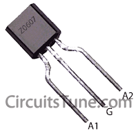
This is a simple ceiling fan regulator circuit diagram. It is used to control the speed of a ceiling fan. In the other words it is an AC motor speed controller circuit, as because its control the speed of a AC motor(Ceiling Fan).  This ceiling fan regulator circuit built with few numbers of parts. The circuit mainly  based on Z0607 TRIAC. This is a low power AC semiconductor device. Generally which is used to controlling speed of low power ac motor speed. 

Circuit Diagram of Ceiling Fan Regulator :

Ceiling fan regulator-motor speed control circuit wiring diagram
Fig: Ceiling fan regulator circuit- AC motor speed controller 
In this ceiling fan regulator circuit, R1=500KΩ is a variable resistor that is used to adjust the fan speed. Capacitor C1 2A104J is a Polyester film capacitor.

Pin Diagram of  TRIAC(T1)- Z0607: 


Z0607 TRIAC Pin Diagram
Fig: Z0607-TRIAC Pin diagram

Pin Diagram of Variable Resistor R1:


Pin Diagram of Variable Resistor
Fig: Pin Diagram of Variable Resistor

Parts List Ceiling Fan Motor Speed Controller circuit:

T1 = Z0607 -TRIAC
D1 = DB3 C312 -DIAC
R1 = 500KΩ -Variable Resistor
R2 = 37KΩ -Resistor
C1 = 2A104J -Polyester film capacitor.
M1 = Single Phase AC Motor (Ceiling Fan)-220V,50Hz


Source
Read More..

Friday, September 26, 2014

Simple Remote Control Mains Switch

As the only electronics engineer in my  =family and circle of friends, it is some-times not possible to evade an appeal for help. This time the request came from a friendly elderly lady in a retirement home. In her room the light switch by the door  and the pull cord above the bed operate the light fitting on the ceiling in the middle of the room. However, she would prefer that her standing lamp was operated  by these switches instead, since she does not actually have a light fitting mounted  on the ceiling. This standing lamp has an  on/of f switch in the power cord and is  plugged into a power point. However, it  stands rather far from the bed so that she  always has to find her way in the dark. A  wireless operated power point is not really  a consideration, because it is just a matter of time before the remote is lost. Or maybe not? 

Circuit Diagram :

Behold a feasible circuit. Buy a wireless power point and an enclosure that is big enough for the remote control and a small piece of prototyping board. On the proto-typing board build the circuit according to the accompanying schematic and (care-fully) open the remote control and solder wires to the push buttons for ‘on’ and ‘off’.  Measure if these are polarised and if that is  the case connect them to the 4N25 opto-couplers as shown in the schematic, where  pin 5 has a higher voltage than pin 4. 

The operation is as follows. The lady operates the pull cord or light switch to turn the light on. This causes the mains voltage to be applied to the transformer. The relay is activated which charges C1. While C1 charges, a small current flows through optocoupler 1. The result is that the ‘on’ button on the remote control is pressed.  The remote control switches the corresponding power point on and to which the  standing lamp is connected. The standing  lamp will therefore now turn on. Capacitor C2 is charged at the same time. If the lady pulls the cord again, or if she operates the  switch near the door, the relay will de-energise and C2 discharges across optocoupler  #2. This operates the ‘off’ contact of the  remote control and the light goes out. 

The remote control continuous to operate from its normal battery and the white enclosure is attached to the ceiling in place of the light fitting. Diode D1 ensures that C1 is discharged when the relay de-energises. D2 ensures that C2 cannot discharge across the relay, but only across optocoupler 2.


Author : Jaap van der Graaff - Copyright :Elektor

Read More..

Friday, December 13, 2013

Digital Volume Control Circuit using MAX5486

Digital Volume Control based IC MAX5486A channel digital volume circuit on IC MAX5486 is shown here. MAX5486 40K digital volume / balance controller that pushbutton interface. The IC bias voltage that eliminated of an external circuitry for purpose and thereby by reduces external count. The IC has an LED indicator driver circuit be used for driving the indicator LEDs indicates level and balance level. The IC operated from or power and in pin TSSOP package. circuit on MAX5486 applied applications like personal audio systems, audio devices, home theatre systems, audio systems, audio systems etc.

The right channel input is applied to the pin8 (high terminal (HR) of internal digital potentiometer of the IC) and left channel input is applied to the pin17 (high terminal (HL) of the second internal digital potentiometer of the IC). Low terminals (pin and 6) of potentiometers are shorted and connected to the mid bias voltage output (pin11) of the IC. at the buffered wiper terminal (pin10) of internal potentiometer and left channel output at the buffered wiper terminal of the second internal potentiometer of the IC. A 1uF capacitor is connected from the bias generator bypass (pin12) to ground. of this capacitor is noise bypassing. of capacitors C4 and C5 are to bypass noise from the VDD and VLOGIC sources. This improves stability and performance of the circuit.

LEDs D1 to D5 are the indicator LEDs indicates volume and balance levels. R1 to R5 limits current through the corresponding LEDs. 1M resistor R6 for activating the indicator LED drivers. LED D6 represents operation mode of IC. When it glows, the IC is in balance mode and when off, the IC in volume mode. Resistor R7 limits through LED D6. volume mode the LEDs work a bar graph indicating volume. balance mode, the centremost LED alone glows when a centred balance. mute mode, all indicator LEDs OFF.

Push button switches S1 to S4 are used for controlling the circuit. Pressing S1 push the IC into mute mode. Push button S4 used between volume mode and balance mode and LED D6 indicated it. Push button S2 and S3 are used for increasing and decreasing volume mode and shifting the balance to left and right balance mode. The Vss pin of the IC is grounded single operation circuit. Shutdown pin (pin6) is tied to the VLOGIC for disabling the shutdown . Connecting the shutdown pin to drive the IC to the shutdown mode.

The output of the MAX5486 is sufficient enough to drive high impedance headphones. For driving low impedance headphones or speakers an amplifier stage be added to the output. power dissipation of MAX5486 is 675mW and consider this point while selecting the loads.
Read More..

Stereo Tone Control using LM1036

Stereo Tone Control using LM1036
This a stereo tone control circuit built using LM1036 IC. This control circuit bass / treble tone level, volume and balance between the right channel and left channel (Input 1 and 2). You can use this circuit for stereo applications such as car radio, television and audio systems, MP3 player, DVD player, ipod and more. An additional control input allows loudness compensation to be made simply. The circuit must be working with a supply voltage of 9V to 15V DC.

Each tone response is defined by a single capacitor chosen to give the desired characteristic. By changing the values ​​of capacitors connected to the tone control unit, you can control bass and treble levels. pin 3 and pin 18 of IC are for acute and pin 6 to pin 15 for bass.
Read More..

Sunday, December 8, 2013

2500W Phase Control

This circuit controls resistive and inductive loads up to 2,500W. Its main functional device is an integrated phase control circuit - Siemens TLE3103. It contains its own power supply, a zero voltage crossing detector circuit and a logic driver. An additional feature is the low voltage input to enable/disable triac firing enabling/disabling the logic driver. The function is as follows: pin13 TLE3103 open (floating), trigger output active, tied to ground trigger output disabled.

2500W Phase Control  Circuit diagram


An UP and a DOWN button control a 32-step digital potentiometer (IC2, AD5228) via the debouncer IC1 (MAX6817). The potentiometer has a power on reset pin which might be tied to ground causing the potentiometer to start at midscale, or to VCC causing it to start at zero scale. The desired function is selectable using jumper JP1. The triac (capable of driving 40A loads) is a bit overkill for the desired power but the BTA41 has an isolated body and therefore handling of the board under voltage is less dangerous as it is with phase on the package. The circuit uses a 68μH inductance, but this might be replaced with a 100 resistor, then replacing the inductance C5 should have a value of 47nF.
Read More..

Wednesday, December 4, 2013

Tone control low noise circuit

Tone control or pre-amplifier is an amplifier circuit supporters. Sometimes some of us do not know where a good amplifier, a raft alone and the results are not much different or even the same. Therefore we must know the character of the advantages and disadvantages of each amplifier equipment.

Tone control low noise here does not mean without noise, but noise compared with the lowest tone control on the market, for example Ronica transistor 4, TL-084, TC-2 LM833 etc.

CSE | Circuit Schematic Electronics

Jump to explanation of each component ...

Potensio 1 serves to regulate the intensity / level of the incoming signal is assisted potensio 2 as balance / counterbalance. Potensio 2 is still installed and is usually an optional component. 1-2uF/250V capacitor R1 is actually a brand name, but I prefer to replace it with a 1K resistor / 5% normal for reasons to avoid hum and interference sensitive. R2 R3 while minimizing interruption to adjust the impedance OP-amp 1. R4 and R5 serves to increase the gain of 1.3 times. Pre amplifiers typically use a strengthening standards by 2 times, but by most of us think it has a noise. So I chose the value of 1.3 times, but the most minimal noise signal from the volume is enough to make the lamp light peak.

For low noise ... Cause of noise in op amp 1, apex audio even eliminate this stage. Can This step is also used as a buffer (jumper R5), the strengthening of a time. Lower values ​​increase the value of R5 or R4 with consequent gains to be less, but remains at a value above 1 times due to input non-inverting path to take, so that the signal and noise can be reduced. R4 can also be replaced with a 10K trimpot and middle leg into the bass range adjuster (bass resonance).

C1 and C6 as a filter to reduce the treble / high frequency of excessive or often called oscillation prevention. R6 is actually an optional component of the impedance a little help customize the system. Ideally the same as the R8 R7 to facilitate give the sign of the gain on potensio panel tone control. C2 and C3 form a series circuit treble filter (high pass filter), its value is greater then the sound that passed the mid. C4 and C5 assisted by R9 and R10 form the low pass filter (filter bass), the greater the value of C is a bass sound that will be missed the soft / low (maximum of 47nF), the smaller the value of c is the bass signal that is passed will further dip (dig-dig, c4 = c5 = 22nF). This value is suitable for 27-33nF, 47nF instead (depending on taste). Pot 3 & 4 pot set treble and bass levels, the greater the greater the value of this potensio gains (bass & treble including potensio volume). R11 adjusts the output impedance, while the R12 and the red LED indicator that shows if the amplifier Peak has been given a full signal.

15V maximum supply. TL074 IC can, but in designing the PCB, IC can be replaced with 2x TL072/NE5532/4558.
Read More..

Sunday, November 24, 2013

Alarm Sound with Control Switch


The heart of this circuit is IC No. 555. When the alert sound was working, even though the switch will continue to be the same, the sound still does not stop immediately.But it will stops automatically, when a set time period,Depending on the resistance of R3, the circuit so I set a time period equal to 1M for 1 minute 6 seconds.
Alarm Sound with Control Switch

The output of IC 555 is triggered by a positive voltage on pin 2,when all switches are connected together.When the something switch is cut off pin 2, it will be negative voltage and the trigger IC 555 will stop. The C1, C4 to protects a noise signal from either switch, which may cause the alarm to be up. This circuit can be used with power supply from 5V to 15V depending on relay sure enough.
Read More..

Thursday, November 21, 2013

Simple Remote Control Tester

Nearly always when a remote control doesn’t work, the underlying problem is elementary: the unit does not emit light. The cause may be dry solder joints, defective LEDs etc., but also a flat battery (perhaps due to stuck key). The human eye is unable to perceive infra-red light. By contrast, an ordinary photo transistor like the BP103 has no problems working in the infrared spectrum, so in the circuit here it simply biases the BC558 which, in turn, makes LED D1 flash in sympathy with the telegram from the remote control. The preset in the circuit determines the sensitivity.

Simple Remote Control Tester
source : Simple Remote Control Tester

Read More..

Saturday, November 16, 2013

Relay Control with MOSFET IRF511

We would like ti show you the circuit is similar to the above, but uses an N-channel MOSFET, as IRF511, 540, 640, etc. instead of the NPN transistor. Smaller MOSFETs can be used, but I do not know the part numbers. I tested the circuit with a IRF640, IRF511, IRFZ34 and REP50N06. The same circuit has three advantages, but requires only a few parts, always off to the relay and do not need a switch debounce.

In operation, when the relay is deactivated, the 100uF capacitor charge up to 6 volts. When the button is pressed, is on the capacitor 6 volts at the gate MOSFET. The capacitor voltage (and gate voltage) of 6 ms should drop to 3 volts in about 200 to move enough time for relay contacts. At very slow relay, a larger capacity. With the ratification of the relay, the contacts 12 volts to the resistance produce valid 3.3K 6 volts at the gate, holding that the relay is self-sufficient. The capacitor is then discharged to zero since the relay contact 12 is connected not to the 15K resistor.

Relay Control with MOSFET IRF511 Circuit Schematic


Relay Control with MOSFET IRF511

When the button is pressed, the capacitor is zero volts to the gate of switching off the relay. There should be no problem making the button again to be the operation of relays, since the gate voltage is only about 1.8 volts when the button is pressed and the MOSFET requires approximately 3.5 volts or more are to start running. But you wait about 1 second or more between pressing a key need, capacitor time to load or unload. Two buttons are displayed, but you could have a number of more parallel to operate the relay from multiple locations
Read More..

Thursday, November 14, 2013

3 Band Tone Control with LF351

3 Band Tone Control circuit uses an op-amp as an amplifier end. Tone Control circuit is a regulator of tone bass, midrange and treble or 3 band called because it can set the three tones. Filter circuit is applied to the series of "Tone Control 3 band" This type baxandal like the title of this article. 

Results filtering regulator tone or tone control baxandal type is good, because there is no signal level is wasted directly into the ground. Range frequency tones generated from Tone Control 3 band was determined by the configuration of the R and C of the filter section baxandal. As an amplifier on Tone Control The set of three band use traditional IC LF351 has slewrate high and high input impedance. For more details, series 3 Band Tone Control as follows.

Figure Series 3 Band Tone Control

3 band tone control

3 Band Tone Control circuit above using LF351 Op-Amp is used to strengthen the signal after filtering by the filter process baxandal. Level tone Bass, Midrange and Treble settings are determined by potensio R1, R2 and R3. Frequency filter in the circuit above baxandal to 50 Hz bass tone, tone Midrange 1 KHz and 10 KHz for Treble tone.
Read More..