Showing posts with label x. Show all posts
Showing posts with label x. Show all posts
Thursday, December 12, 2013
TDA2005 2 X 20 Watt Power Amplifier
This time, there is a series of audio amplifer 20W as well, but using IC TDA 2005 as a series of his base amplifier.
The series of 2x20 Watt Audio Power Amplifier using TDA2005 can you see in the picture below.
The series of 2x20 Watt Audio Power Amplifier using TDA2005 can you see in the picture below.
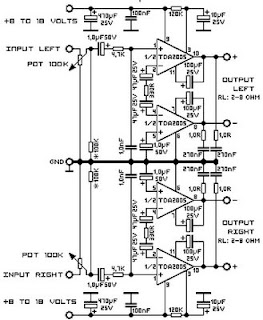
Technical Data:
Performance of TDA2005M: (for this circuit); At 4.14 V supply voltage: 2 x 20 watts (stereo) into 4 Ohms.
Distortion: Approx. 0.2% at 4 Watts into 4 ohm load.Frequency Range: Approx. 20 Hz to 22 KHz.
Input Sensitivity: Approx. maximum 150 mV rms. .
Power supply: + 8 to 18 volts, approx. 3.5 Amps maximum per channel.

Monday, December 2, 2013
TDA7384 4 x 22W car power amplifier
TDA7384 - 4 x 22W car power amplifier
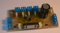 If connect to car battery where operating voltage is about 13.2V, then each channel can give 22W(4Ω) – what is more than enough for me. This amplifier I probably will use to test audio processor TDA7313 which is stil in development phase.
I didn’t find much information about this chip on the internet so I decided to built it and try on my own. As datasheets of TDA7384 says it is low distortion, low output noise, low external component count. Also has Stand-By function and Mute function. It has several protections like from output short circuit to GND or to Vs, capable to handle very inductive loads, thermal limiter, load dump voltage. TDA7384 is an AB power amplifier cased in flexiwatt25 (eagle library is included in project archive) package wich is designed for high end car radio applications. It allows rail to rail output voltage swing with no need of boot-strap capacitors.
 |
| Schematics TDA7384 |
I have followed the schematic in datasheed when building circuit. In datasheet you may also find PCB layout but it is two layered and didn’t fit to may box I’ve chosen. So I have made single sided PCB 50X100mm.
| PCB TDA7384 amplifier |
As I put pins on PCB for ST-BY and Mute but I not using them, I connected these pins to VCC like it is shown in PCB view. According to datasheet St-By and Mute turns off amplifier if signal in input is lower than 3.5V. So it is recommended to connect these pins to Vcc if not used.
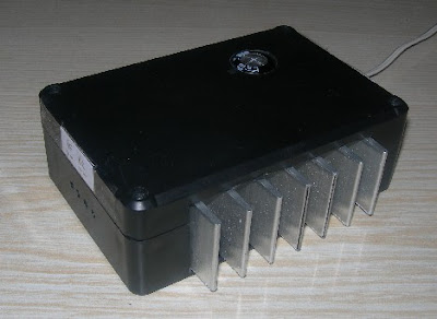
Maximum power dissipation of chip is 80W(Tcase=70ºC), so it can handle 4 channels working at power of 20W each. But of course chip in a box doesn’t have good ventilation so I’ve put a radiator to ensure that amplifier effectively dissipates heats. I didn’t try to load amplifier to maximum to se if it doesn’t heat up to much. But at normal sound level it stays warm what is normal.
 |
| On box amplifier |
Dont forget to put thermal paste between chip and radiator to ensure lower thermal resistance. And here we go – brand new power amplifier ready to go:
 |
| Already to use |
source: [link]
Subscribe to:
Posts (Atom)