Thursday, November 21, 2013

Traffic Light 20 Chanel based on 74LSxx

Traffic Light 20 Chanel based on 74LSxxTraffic Light 20 Chanel based on 74LSxx


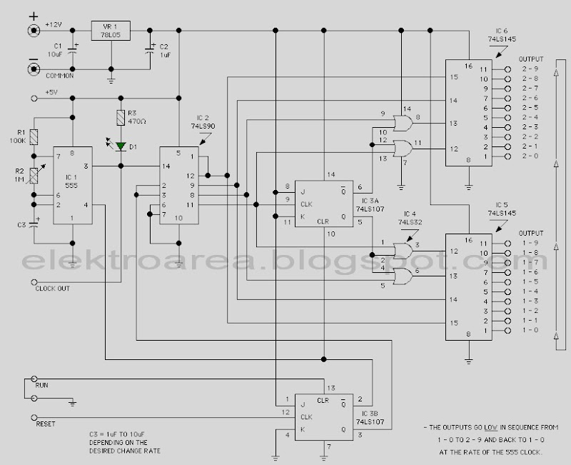
This view of the proposed traffic Light 20 Chane based only on family and 74LSxx IC 555 as clock source. It is a digital logic circuit. To construct the traffic light rangkaian Control requires no programming of microcontrollers.


This page features a circuit that has twenty open collector outputs that turn on one at a time in a continuous sequence. The circuit make use of the family 74LSxx TTL integrated logic devices. The circuits are designed to drive light emitting diodes or low current and low voltage incandescent lamps, but can also lead to other charges of 80 milliamps.


notes:

  • The low output go in sequence from 1 - 0 and back to 1 -0

  • At the clock rate of the 555 timer
  • c3 = 1uf to 10uf depending on the rate of change desured
  • R2 (Variable resistor) in use to determine the timer
Read More..

Wednesday, November 20, 2013

Amplifier Circuit with IC AN7133

 *note:this is stereo amplifier
 
This circuit is stereo power amplifier . Voltage input or Supply voltage with dual voltage minimum 6 volt , and maximum 18 volt . You cant  use triple voltage in this amplifier and must DC voltage not AC voltage . Maximum output power 2 X 15 watt  with minimum impedance 4 ohm . You can use this amplifier on car commonly called car amplifier, on Personal Computer (PC) , on small room , etc.

See this schematic amplifier circuit with IC AN7133 below :


Read More..

Schematic Audio Power Amplifier with IC TDA2822

TDA2822 is manufactered by PHILIPS , its based on this amplifier . Minimum voltage 3 volts and maximum voltage 15 volts. Power output 2 x 1,8 stereo with 4 Ohm impedance. Quiescent current 6 mA , sensitive input is 30 Hz to 18 kHz. See circuit diagram below :

Read More..

Automatic Light Controller Using 7806

Voltage
regulator ICs (78xx series) provide a steady output voltage, as
against a widely fluctuating input supply, when the common terminal is
grounded. Any voltage about zero volt (ground) connected in the common
terminal is added to the output voltage. That means the increase in the
common terminal voltage is reflected at the output. On the other hand,
if the common terminal is disconnected from the ground, the full input
voltage is available at the output. This characteristic is utilised in
the present circuit.

When the common terminal is connected to
the ground,the regulator output is equivalent to the rated voltage, and
as soon as the terminal is disconnected from the ground, the output
increases up to the input voltage. The common terminal is controlled by a
transistor, which works as a switch on the terminal. For automatic
control of light, a light-dependent resistor (LDR1) is connected to the
base of the transistor. In this way, the voltage regulator is able to
operate a light bulb automatically as per the ambient light.

To
derive the power supply for the circuit, the 50Hz, 230V AC mains is
stepped down by transformer X1 to deliver a secondary output of 12V, 250
mA. The secondary output of the transformer is applied to a bridge
rectifier comprising diodes D1 through D4, filtered by capacitor C1 and
fed to the input terminal of the regulator (IC1). The common terminal
(pin 2) of IC1 is connected to the ground line of the circuit through
transistor BC557 (T1). The transistor is biased by R2, R3, VR1 and LDR1.


Automatic Light Controller Using 7806 circuit schematic

The
grounding of IC1 is controlled by transistor T1, while light is sensed
by LDR1. Using preset VR1, you can adjust the light-sensing level of
transistor T1. The output of IC1 is fed to the base of transistor T2
(through resistor R4 and zener diode ZD1) and relay RL1. LED1 connected
across the positive and ground supply lines acts as a power-‘on’
indicator. Normally, the resistance of LDR1 is low during daytime and
high during nighttime. During daytime, when light falls on LDR1, pnp
transistor T1 conducts.

The common terminal of IC1 connects to
the ground and IC1 outputs 6V. As a result, transistor T2 does not
conduct and the relay remains de-energised. The light bulb remains ‘off’
as the mains connection is not completed through the relay contacts.
During nighttime, when no light falls on LDR1, it offers a high
resistance at the base junction of transistor T1. So the bias is greatly
reduced and T1 doesn’t conduct. Effectively, this removes the common
terminal of IC1 from ground and it directs the full input DC to the
output. Transistor T2 conducts and the relay energises to light up the
bulb as mains connection completes through the relay contacts.

As
LDR1 is in parallel to VR1 R3 combination, it effectively applies only
half of the total resistance of the network formed by R3, VR1 and LDR1
to the junction at T1 in total darkness. In bright light, it greatly
reduces the total effective resistance at the junction. The circui t is
simple and can be assembled on a small general-purpose PCB. Use a
heat-sink for IC1. Make sure that LDR1 and the light bulb are well
separated. The circuit can be used for streetlights, tubelights or any
other home electrical lighting system that needs to be automated.
Read More..

The Importance of a Good Auto Sound System

If you spend a good deal of time in you car, and yes, the morning commute to work and the evening commute home each and every day definitely counts, you are probably more than slightly aware of the benefits of having a good auto sound system. Your sound system is your companion in your travels most of the time. Even those who have children often spend a great deal of time driving alone.


The Importance of a Good Auto Sound SystemFor those long and sometimes lonely miles your auto sound system is the voice of reason, the energetic beat, and the information that keeps you up on current events, weather forecasts, and what is going on in the world of the rich and famous. Even if you arent all that into music there is the wide and wonderful world of talk radio that keeps many of us informed and inflamed about issues that are important to us and causes which we feel passionately about.

The proper auto sound system affects the way we hear everything that comes through our radios. It doesnt really matter if you have the latest and greatest of subscription programs, XML programming, or even digital radio if your sound system is poor the quality of your programming will never reach your ears. Your sound system is the difference in standard sounds coming through your speakers and excellence making its way to your ears.

Contrary to popular belief however, you do not have to have the loudest sound system in order to have the best sound system. The truth of the matter is that once the music is so loud it ceases to sound like music and comes across to those inside and outside of your automobile more as noise than the wonderful music it may be in other circumstances. While there are many who enjoy the throbbing and jumping sounds that come from over emphasized bass, there is something to be said for an auto sound system that is well rounded and balanced. A good sound system will make all aspects of the music sound better and not just a certain few.

The important thing about sound systems arent the price that they command, the bass that they flaunt, or even the most minute details of the making and manufacturing of the sound system. The true beauty of a sound system lies in the fact that it should be music to your ears. You and you alone can choose the sound system that you like best as every person has different things they will listen for and enjoy in not only their music but also their sound systems. I love many different types of music and as a result will tend to listen to several different music genres as well as a stint of talk radio on several different systems and elect the one that sounds the best on the most of the music platforms and genres I prefer. I recommend a course of action similar to this to all who are interested in purchasing an auto sound system for their vehicle.

One thing that often gets overlooked is how much time we really spend in our vehicles in the course of a week. Most people pay very little time, money, or attention the particular stereos we put into our vehicles when in reality we spend nearly as much time each week listening to our auto sound systems as we do watching the televisions in our home. Music is all around us and it deeply affects and enhances our joys, our sorrows, even our romance. For those reasons, shouldnt we invest as much, if not more, time and energy in a great auto sound system as we do in a television for our homes?

By taking the time to get the perfect sound system for our vehicles when we first purchase our automobiles we will enjoy the maximum benefit our sound systems can provide. By enjoying our sound system, more people are willing to hang on to their vehicles longer which actually saves a great deal of money in the long run while also increasing your overall enjoyment of your time spent commuting to and from work each and every day.

Read More..

Tuesday, November 19, 2013

14W Class A Amplifier Circuit with 2N3055

14W Class A Amplifier Circuit with 2N305514W Class A Amplifier Circuit with 2N3055


This class A amplifier circuit requires a preamp as it hasnt got much gain. Requires large heat sinks and a large transformer and a source of great power and wiring carefully, but the end is very simple and sounds great. The zener diode disclaims any wave from the power supply, but still just want a wave of 10mV max. The ripples reaching the entrance is amplified, so the zener get rid of that, but there is still dominated him to reach the power stage.


Many early amplifiers operated in Class A, but as 10W power output rose above the problems of heat dissipation and design of the power supply caused most manufacturers to turn to the simplest, arrangements more efficient class B and put up with the consequent decrease in the perceived quality of output. Why Class? Because, when biased in class A, the transistors are always on, always ready to respond instantly to an input signal. Class B and Class AB output stage requires a microsecond or more on. The kind of a cleaner operation allows operation under high voltage swing that occurs when the transient audio signal feed difficult loads. Your amplifier is basically simple, as shown in the block diagram.
Read More..

555 timer chip tester

555 timer chip tester
IC 555 timer tester is a simple circuit that serves to test the condition of IC 555. 555 timer circuit tester, in principle, start the timer 555 in astable multivibrator mode. As an indicator of the status of the timer 555 good condition or damaged to use 2 pieces LED which will light up in a blink alternately when the timer 555 in good condition. 

And only one will turn on or off all the timer 555 when the condition is broken. 555 timer circuit tester is powered using 9 Volt DC voltage source. Complete circuit tester 555 as follows.

tester schematic circuit 55
Tester schematic
How to use 555 timer tester is in conjuction with IC 555 to test the existing IC socket according to the orderbutton. Then activate the power switch to begin testing the 555 timer ic. Then live we observe the LED indicators 2buah before, whether flashing alternately (good) or not blink or even die all (timer 555 damaged).
Read More..