Showing posts with label regulator. Show all posts

Friday, October 24, 2014

Low drop Regulator with Indicator Circuit Diagram

Even today much logic is still powered from 5 volts and it then seems obvious to power the circuit using a standard regulator from a rectangular 9-V battery. A disadvantage of this approach is that the capacity of a 9-V battery is rather low and the price is rather high. Even the NiMH revolution, which has resulted in considerably higher capacities of (pen-light) batteries, seems to have escaped the 9-V battery generation. It would be cheaper if 5 volts could be derived from 6 volts, for example. That would be 4 ‘normal’ cells or 5 NiMH- cells. Also the ‘old fashioned’ sealed lead- acid battery would be appropriate, or two lithium cells.
 
Circuit diagram : 
Low-drop Regulator with Indicator-Circuit-Diagram
Low-drop Regulator with Indicator Circuit Diagram
 
Using an LP2951, such a power supply is easily realised. The LP2951 is an ever- green from National Semiconductor, which you will have encountered in numerous  Elektor Electronics designs already. This IC can deliver a maximum current of 100 mA at an input voltage of greater than 5.4 V. In addition to this particular version, there are also versions available for 3.3 and 3 V output, as well as an adjustable version.  In this design we have added a battery indicator, which also protects the battery from too deep a discharge. As soon as the IC has a problem with too low an input voltage, the ERROR output will go low and the regulator is turned off via IC2d, until a manual restart is provided with the RESET pushbutton.
 
The battery voltage is divided with a few resistors and compared with the reference voltage (1.23 V) of the regulator IC. To adapt the indicator for different voltages you only need to change the 100-k resistor. The comparator is an LP339. This is an energy-friendly version of the LM339. The LP339 consumes only 60 µA and can sink 30 mA at its output. You can also use the LM339, if you happen to have one around, but the current consumption in that case is 14 times higher (which, for that matter, is still less than 1 mA).
 
Finally, the LP2951 in the idle state, consumes about 100 µA and depend- ing on the output current to be deliv- ered, a little more. 


Read More..

Monday, October 20, 2014

Ceiling Fan Regulator Motor Speed Control Circuit Diagram

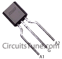
This is a simple ceiling fan regulator circuit diagram. It is used to control the speed of a ceiling fan. In the other words it is an AC motor speed controller circuit, as because its control the speed of a AC motor(Ceiling Fan).  This ceiling fan regulator circuit built with few numbers of parts. The circuit mainly  based on Z0607 TRIAC. This is a low power AC semiconductor device. Generally which is used to controlling speed of low power ac motor speed. 

Circuit Diagram of Ceiling Fan Regulator :

Ceiling fan regulator-motor speed control circuit wiring diagram
Fig: Ceiling fan regulator circuit- AC motor speed controller 
In this ceiling fan regulator circuit, R1=500KΩ is a variable resistor that is used to adjust the fan speed. Capacitor C1 2A104J is a Polyester film capacitor.

Pin Diagram of  TRIAC(T1)- Z0607: 


Z0607 TRIAC Pin Diagram
Fig: Z0607-TRIAC Pin diagram

Pin Diagram of Variable Resistor R1:


Pin Diagram of Variable Resistor
Fig: Pin Diagram of Variable Resistor

Parts List Ceiling Fan Motor Speed Controller circuit:

T1 = Z0607 -TRIAC
D1 = DB3 C312 -DIAC
R1 = 500KΩ -Variable Resistor
R2 = 37KΩ -Resistor
C1 = 2A104J -Polyester film capacitor.
M1 = Single Phase AC Motor (Ceiling Fan)-220V,50Hz


Source
Read More..

Friday, February 7, 2014

Three Phase Generator regulator

This regulator was designed for use with a  generator with a higher output voltage. This  type of generator can be found on some boats  and on vehicles for the emergency services.  They are really just an adapted version of the  standard alternator normally found in cars.  The field winding is connected to the 12 V  (or 24 V) battery supply, whereas the generator winding is configured for the AC grid  voltage (230 V or 115 V). This AC voltage now  has to be kept stable via the 12 V field winding. Although it’s perfectly possible to use a  switching regulator for this, we deliberately  chose to use the old and trusted 723.
Circuit diagram :
Regulator for Three-Phase Generator-Circuit Diagram
Regulator for Three-Phase Generator Circuit Diagram
The generator is a three-phase type, with the  field winding rated for 12 VDC. The output voltage of the generator depends on its revs  and the current through the field winding.  Since the output voltage is relatively high, it  is fed via opto-couplers to the 723, which is  used in a standard configuration.  The output is fed via driver T1 to two  2N3055’s, connected in parallel, which sup-ply the current to the field winding. In the prototype we used TLP620 opto-couplers. These are suitable for use with alternating voltages because they have two anti-parallel LEDs at the input. The regulation works  quite well with these, with the output volt-age staying within a small range across a wide  range of revs.
However, the sensitivity of the two internal  LEDs can differ in this type of opto-coupler,  since it’s not always possible to ensure during  the manufacturing process that the distance  between each LED and the phototransistor is  exactly the same. For a more precise regulation it would be better to use two individual  opto-couplers per phase, with the inputs connected in anti-parallel and the outputs connected in parallel.
In order to ensure that there is sufficient isolation between the primary and secondary side  you should make a cutout in the PCB underneath the middle of each opto-coupler. Instead of a BD136 for T1 you could also use  a TIP32 or something similar. For T2 and T3  it’s better to use a type with a plastic casing,  rather than a TO3 case.


http://www.ecircuitslab.com/2012/04/regulator-for-three-phase-generator.html
Read More..

Digital Fan Regulator

The circuit presented here can be used to control the speed of  fans using induction motor. The speed control is nonlinear, i.e. in steps. The current step number is displayed on a 7-segment display. Speed can be varied over a wide range because the circuit can alter the voltage applied to the fan motor from 130V to 230V RMS in a maximum of seven steps.  The triac used in the final stage is fired at different angles to get different voltage outputs by applying short-dura-tion current pulses at its gate. For this pur-pose a UJT relax-ation oscillator is used that outputs sawtooth waveform. This waveform is coupled to the gate of the triac through an optocoupler (MOC3011) that has a triac driver output stage. 

Pedestal voltage control is used for varying the firing angle of the triac. The power supply for the relaxation oscillator is derived from the rectified mains via 10-kilo-ohm, 10W series dropping/limit-ing resistor R2.  The pedestal voltage is derived from the non-filtered DC through optocoupler 4N33. The conductivity of the Darlington pair transistors inside this optocoupler is varied for getting the pedestal voltage. For this, the positive sup-ply to the LED inside the optocoupler is connected via different values of resistors using a multiplexer (CD4051). 

Circuitdiagram:
Digital Fan Regulator Circuit Diagram

The value of resistance selected by the multiplexer depends upon the control in-put from BCD up-/down-counter CD4510 (IC5), which, in turn, controls forward bi-asing of the transistor inside optocoupler 4N33. The same BCD outputs from IC5 are also connected to the BCD-to-7-seg-ment decoder to display the step number on a 7-segment display.  NAND gates N3 and N4 are config-ured as an astable multivibrator to produce rectangular clock pulses for IC5, while NAND gates N1 and N2 generate the active-low count enable (CE) input using either of push-to-on switches S1 or S2 for count up or count down operation, respectively, of the BCD counter. 

Optocoupler 4N33 electrically isolates the high-voltage section and the digital section and thus prevents the user from shock hazard when using switches S1 and S2. BCD-to-7-segment decoder CD4543 is used for driving both common-cathode and common-anode 7-segment displays. If phase input pin 6 is ‘high’ the decoder works as a common-anode decoder, and if phase input pin 6 is ‘low’ it acts as a common-cathode decoder.  Optocoupler 4N33 may still conduct slightly even when the display is zero, i.e. pin 13 (X0, at ground level) is switched  output pin 3. To avoid this problem, adjust preset VR1 as required using a plastic-handled screwdriver to get no output at zero reading in the display. 

http://www.ecircuitslab.com/2011/10/digital-fan-regulator.html
Read More..

Monday, December 16, 2013

Workings of STR IC Regulator Power Supply

The meaning STR in this article for example is a Sanken regulator series and Fairchild series STR-F/G/W KA05Q Is an ic Quasy Resonant Flyback (QRF) Swiching Regulator comprising (a) control IC and (b) power MOSFETs that are packed into a single unit. The regulator is designed so that only requires a few external components.

How it works :
A. UVLO (under voltage lock out)
Regulators will start working when the voltage Vcc start-up on pin-4 reaches 16V. Once the power supply voltage Vcc further work will be reimbursed through a switching transformer supplied from a diode rectifier. At the time the circuit was working when the voltage Vcc is less than 15V, the regulator controls will still work. regulator will stop working (protectionism) if the supply voltage Vcc drops to less than 11V.
  
2. Feedback control (pin-1)
Workings of regulator ic STR
PWM regulators work using the system, wherein the output voltage B + to stable controlled by the feedback circuit of the output voltage B + >>> >>> photo-coupler pin-1. A capacitor mounted on the pin-1 is used to prevent noise disturbance if anyone does not interfere with the working system.

  
3. Soft start (pin-5)
When the power is turned on first, then the circuit has not been working behind the Uman because there is no output voltage B +. This causes a heavy current on the MOSFET start. To prevent this, the regulator is equipped with soft start circuit internally and an external filter kapasitr.
If the power supply is used to monitor for example, the frequency of the regulator needs to be synchronized. External synchronization signal can be input through pin-5s
  
4. Protectors
Regulators are equipped with all sorts protector.
  • Over-current protector (OCP) or Over Load protector (OLP). For example, if there is damage to flyback or def yoke, it will cause the load voltage B + over. If there is such a case the regulator will die protectionism so that IC is not damaged. For over current sensor is a resistor with a small value that is placed on pin-2 to the ground.
  • Short protector. If the output voltage B + short, the regulator turns off protectionism.
  • Over-voltage protectors (OVP). Regulators are not equipped with a surge protector so if the feedback path disconnected can cause the output voltage of the transformer switching regulator power up or damaged .. With OVP protectionist regulator will die if the voltage supply Vcc pin-4 rise above 22.5v.
  • Thermal protector. Regulators will stop working if the temperature reaches 140 degrees Celsius.
6. Auto start.
Regulators will start automatically if the auto turns itself (protectionism) after OVP or OCP


read also ->>>> Troubleshooting STR IC Regulator Power Supply
Read More..

Tuesday, December 10, 2013

Adjustable Switching Regulator Circuit with LM2576

The Adjustable Switching Regulator Circuit with LM2576 are monolithic integrated circuits that provide all the active functions for a step-down (buck) switching regulator, capable of driving 3A load with excellent line and load regulation. These devices are available in fixed output voltages of 3.3V, 5V, 12V, 15V, and an adjustable output version.
LM2576 IC Package
LM2576 IC Package
Requiring a minimum number of external components, these regulators are simple to use and include internal frequency compensation and a fixed-frequency oscillator. The Adjustable Switching Regulator Circuit with LM2576 offers a high-efficiency replacement for popular three-terminal linear regulators. It substantially reduces the size of the heat sink, and in some cases no heat sink is required.


Adjustable Switching Regulator Circuit with LM2576
IC Switching Regulator Circuit with LM2576

A standard Adjustable Switching Regulator Circuit with LM2576 of inductors optimized for use with the LM2576 are available from several different manufacturers. This feature greatly simplifies the design of switch-mode power supplies.

Other features include a guaranteed ±4% tolerance on output voltage within specified input voltages and output load conditions, and ±10% on the oscillator frequency. External shutdown is included, featuring 50 μA (typical) standby current. The output switch includes cycle-by-cycle current limiting, as well as thermal shutdown for full protection under fault conditions.

Features Adjustable Switching Regulator Circuit with LM2576 :
- 3.3V, 5V, 12V, 15V, and adjustable output versions
- Adjustable version output voltage range,1.23V to 37V
- Guaranteed 3A output current
- Wide input voltage range, 40V up to 60V for HV version
- Requires only 4 external components
- 52 kHz fixed frequency internal oscillator
- TTL shutdown capability, low power standby mode
- High efficiency
- Uses readily available standard inductors
- Thermal shutdown and current limit protection
- P+ Product Enhancement tested
Read More..