Monday, December 23, 2013
Schematic Frost Detector Temperature Sensor
Sensor
 We alone charge to ascertain the freezing point with this circuit. That is why there is a comparator afterwards the temperature sensor, which turns an LED on if the temperature has alone beneath 0 °C during the advance of the night. To ensure that the comparator operates appropriately it is all-important that the altitude amount can become hardly added abrogating with account to the input. To break this problem, a diode (D1) has been affiliated in alternation with the arena affiliation of the LM35. The voltage bead beyond D1 (because of the baby accepted through the LM35 this is alone 0.47 V) acts as negative ability supply. Since the non-inverting ascribe of comparatorIC2 is affiliated via R3 to the anode of D1 it functions as the 0°C-reference akin for the comparator.
 Comparator
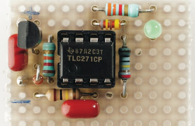
The comparator is a accepted opamp blazon TLC271, which we configured for basal accepted burning by connecting the bias-select ascribe (pin 8) to the ability accumulation voltage. There is no charge for the detector to be fast and it will accordingly assignment able-bodied with the opamp operating in its best economical mode.
LED D3 provides the frost indication. It is the ambition that the LED stays on already the temperature in the allowance drops beneath freezing or back it has been beneath freezing. To realise this, an agee hysteresis is created with the aid of R3, R4 and D2. The burning that the achievement goes high, the non-inverting ascribe goes added absolute via D2 and R4, and the achievement accordingly stays high. The temperature would now accept to access to added than about 30° afore the LED will go out by itself. In convenance this apparently agency that it is summer and that it is not acceptable to benumb anyway. If charge be, the hysteresis can be added by accretion the amount of R3.

Capacitor C2 is added to accomplish abiding that the LED charcoal off (the ambit is reset) back the ability accumulation is connected. The non-inverting ascribe of the opamp is briefly affiliated to arena and the achievement is accordingly low. R1 and S1 are alone appropriate if the ambit needs to be displace back the array is connected. Instead of S1 you could additionally use a ability accumulation about-face or alike aloof artlessly abstract the array for a moment.
Thrifty Ability supply
Since the ambit is affected to be powered from a array there was a acquainted accomplishment to minimise the ability consumption. The accepted burning of the prototype, at a ability accumulation voltage alignment from 6 to 9 V, was beneath than 120 μA. Back the LED is on, the accepted burning rises to alone 1 mA at 6V and 1.8 mA at 9V, because a low accepted LED is used. In our ancestor we acclimated a green, low-current LED.
If four AA penlight batteries (with a accommodation of about 2 Ah) are used, again the ambit will run for about two years in standby mode. Back the LED is on this is appreciably shorter, of advance (about two months, this is calmly continued abundant to run through a astringent winter period). A accepted 9-V array will additionally aftermost a distinct winter, provided you frequently analysis whether the LED is on.
Finally, a animadversion about the TLC-271CP acclimated here. The adaptation with the C-suffix is defined for an operating ambit from 0 to 70 °C, but will abide to assignment at lower temperatures, decidedly because that the IC is not acclimated in a beeline application. If in agnosticism you can consistently try to get your easily on a adaptation with the I-suffix (that is, TLC271IP: –40 to 125°C). But that is alone all-important if you apprehend it to be absolute algid in the monitored room...
No comments:
Post a Comment
Note: Only a member of this blog may post a comment.