Showing posts with label video. Show all posts
Showing posts with label video. Show all posts
Friday, October 24, 2014
TV Video Transmitter Circuit Diagram
This circuit is a video transmitter that has many uses, such as video cameras, security cameras, satellite receivers, DVD, Video Games, etc. .. The circuit transmits 470-580MHz and can be tuned in the UHF channels 21-34. The video transmitter can reach up to 300 meters in open field using a wire antenna of 10-20 cm.
TV Video Transmitter Circuit Diagram

Video Transmitter
Transmitter can work with a voltage from 9 to 15 volts. However, you can also use a 9v battery. Oscillator is based around BF199 and BFR90 is the RF transistors. If necessary, the transmission power can be increased by replacing with BFR90 transistor 2N3886.
Video Transmitter
Transmitter can work with a voltage from 9 to 15 volts. However, you can also use a 9v battery. Oscillator is based around BF199 and BFR90 is the RF transistors. If necessary, the transmission power can be increased by replacing with BFR90 transistor 2N3886.

Tuesday, November 12, 2013
Video IF circuit TV

The main function of the video IF is to change the 38.0 MHz IF signal into the CVBS signal which later fed into the sound and video to the chroma.
VIF section consists of a series as follows:
IF amplifier
This section serves to strengthen the signal until the signal level is required. IF amplifier is equipped with AGC (Automatic Gain Controller) which controls the strengthening of the IF amplifier so that a constant amplitude output video. Amplifier frequency range from 32 ~ 60 MHz makes this amplifier suitable for applications multistandar.
PLL demodulator and VCO (voltage control oscillator)
IF signal is separated with the help of PLL detector. PLL detector produces a phase reference signal with the IF signal carrier and about 60 KHz bandwidth is determined by PLL loopfilter pin 37. Obtained by comparing the frequency demodulation reference signal with the incoming IF signal. Are required reference frequency (38.0 MHz) generated by the VCO. Appropriate VCO frequency is determined by system calibration using the crystal as a reference. PLL can detect the IF frequency up to ± 1 MHz based on FPLL (Frequency Phase Lock Loop System) which will provide an output signal to the PLL loopfilter for the difference frequency is obtained. If the phase IF signal with a reference signal, the signal is transmitted to the demodulator. Demodulator to control the positive and negative modulation, the selection made by the IIC bus. Low pass filter after the output signal demodulator eliminates the demodulation is not required to process the video.
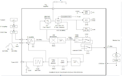
Video Buffer
Video buffer to produce a video output with an amplitude of the right and keep the video output from the noise peak occurring. The bandwidth of the video buffer at least 6 MHz. In the video there are White spot clamp buffer (for positive modulation) and the noise inverter Clamp (for negative modulation) which keeps the amplitude of the video does not exceed the typical price.
Subscribe to:
Posts (Atom)