Tuesday, February 25, 2014
Browse »
home»
blinking
»
leds
»
Blinking LEDs diagram project

Blinking LEDs diagram project
Listening to music on my pc (proudly using WINAMP), I was wondering how would be to have some leds blinking with the sound that came out from the P2 connector, so I decided to make a simple circuit to do that. It worked pretty fine, so I decided to write a HowTo telling step-by-step how to do it. Hope you enjoy it!
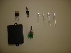
Material and Equipment:
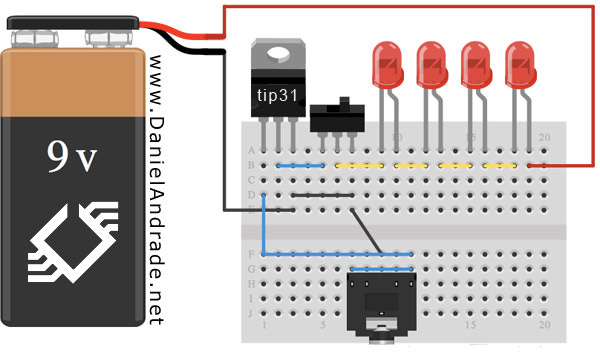
This project will work this way, you connect 4 leds in the +12V from your computer, they are soldered to a 2 position switch that will connect to a component called TIP31, this component gets the intensity transmitted by the P2 connector, and with that, makes the leds blink with the music.
You can follow this scheme (there are 3 different ones, hope you understand it).

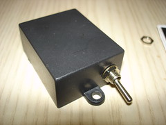
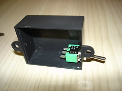
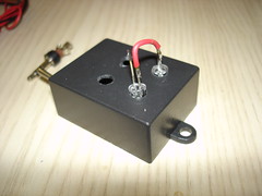
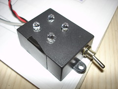
For this project, I decided to install everything inside a small black box I had here, so I made 6 holes on it. Four in the top for leds and one in each side for the switcher and cables. You can follow by the pictures:


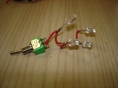
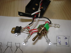
With the box ready, its time to connect everything. I started with the leds, soldering one small cable connecting each one, so would be easier to arrange them inside the box after.
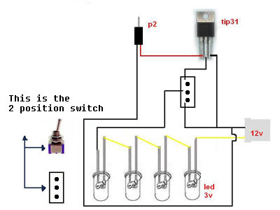
After connecting all leds, you must connect the cable coming from the leds to the center pin of the switcher. One side of the switcher goes to the middle pin of the Tip31 component, and the other one goes to ground cable.
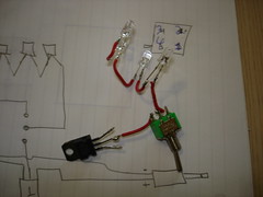
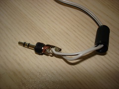
Now it’s time to make the P2 connector. You can see that the P2 connector have 3 pins, they are, left channel, right channel and ground. So you have to decide to get the left or right channel and connect with the left pin from the Tip31. Remember that if you connect the P2 using the left channel, if only the right is enabled on the computer, this circuit won’t work. Usually the ground pin is the bigger one, and the other are small and similar. You have to connect the ground from P2 connector to the right pin of the Tip31 (right pin from Tip31 is ground)
On the other pin from the switcher, you must connect to the ground from Tip31. If the switcher if closing circuit with the Tip31, the leds will only blink if there is any signal coming from the P2 connector, and if it’s in the other direction, the leds will be always ON.
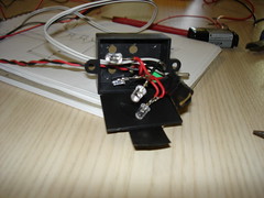
Now it’s time to put everything together in the box, as you can see in this picture, it’s not very organized, but after closing the box, it’ll look much better.
Job is done!!


Material and Equipment:
- 4 LEDs (any collor)
- P2 plug
- 2 position switch
- TIP31 component
- Box to put all the stuff (if you want)
- Soldering iron and accessories
- Cable
This project will work this way, you connect 4 leds in the +12V from your computer, they are soldered to a 2 position switch that will connect to a component called TIP31, this component gets the intensity transmitted by the P2 connector, and with that, makes the leds blink with the music.
You can follow this scheme (there are 3 different ones, hope you understand it).
For this project, I decided to install everything inside a small black box I had here, so I made 6 holes on it. Four in the top for leds and one in each side for the switcher and cables. You can follow by the pictures:
With the box ready, its time to connect everything. I started with the leds, soldering one small cable connecting each one, so would be easier to arrange them inside the box after.
After connecting all leds, you must connect the cable coming from the leds to the center pin of the switcher. One side of the switcher goes to the middle pin of the Tip31 component, and the other one goes to ground cable.
Now it’s time to make the P2 connector. You can see that the P2 connector have 3 pins, they are, left channel, right channel and ground. So you have to decide to get the left or right channel and connect with the left pin from the Tip31. Remember that if you connect the P2 using the left channel, if only the right is enabled on the computer, this circuit won’t work. Usually the ground pin is the bigger one, and the other are small and similar. You have to connect the ground from P2 connector to the right pin of the Tip31 (right pin from Tip31 is ground)
On the other pin from the switcher, you must connect to the ground from Tip31. If the switcher if closing circuit with the Tip31, the leds will only blink if there is any signal coming from the P2 connector, and if it’s in the other direction, the leds will be always ON.
Now it’s time to put everything together in the box, as you can see in this picture, it’s not very organized, but after closing the box, it’ll look much better.
Job is done!!
Subscribe to:
Post Comments (Atom)
No comments:
Post a Comment
Note: Only a member of this blog may post a comment.